Method of arranging an electric accumulating system close to a platform of a vehicle and hybrid propulsion vehicle

a technology of electric accumulating system and platform, which is applied in the direction of battery/fuel cell control arrangement, capacitor propulsion, battery/cell propulsion, etc., can solve the problems of limiting the useful space, limiting the placement of the accumulating system within the vehicle, and limiting the storage of electric power by the accumulating system

Active Publication Date: 2013-03-19
SPAN FERRARI SPA
View PDF36 Cites 57 Cited by
  • Summary
  • Abstract
  • Description
  • Claims
  • Application Information

AI Technical Summary

Benefits of technology

[0009]It is the object of the present invention to provide a method for arranging an electric accumulating device in proximity of a vehicle floor and a hybrid propulsion vehicle, which are free from the above-described drawbacks and are both easy and cost-effective to be implemented.

Problems solved by technology

The placement of the accumulating system within the vehicle may be very complex especially in the event of a high-performing sports vehicle having very reduced internal spaces.
In known vehicles, the above-mentioned constraints force the arrangement of the batteries of the accumulating system in not optimal positions, also severely limiting the useful space; consequently, the ability of storing electric power by the accumulating system is limited and thereby the chances of using the electric machine are also reduced.

Method used


Image

  • Method of arranging an electric accumulating system close to a platform of a vehicle and hybrid propulsion vehicle
  • Method of arranging an electric accumulating system close to a platform of a vehicle and hybrid propulsion vehicle
  • Method of arranging an electric accumulating system close to a platform of a vehicle and hybrid propulsion vehicle

Examples


Embodiment Construction

[0009]It is the object of the present invention to provide a method for arranging an electric accumulating device in proximity of a vehicle floor and a hybrid propulsion vehicle, which are free from the above-described drawbacks and are both easy and cost-effective to be implemented.

[0010]According to the present invention, there are provided a method for arranging an electric accumulating device in proximity of a vehicle floor and a hybrid propulsion vehicle as claimed by the attached claims.

BRIEF DESCRIPTION OF THE DRAWINGS

[0011]The present invention will now be described with reference to the accompanying drawings, which illustrate some non-limiting exemplary embodiments thereof, in which:

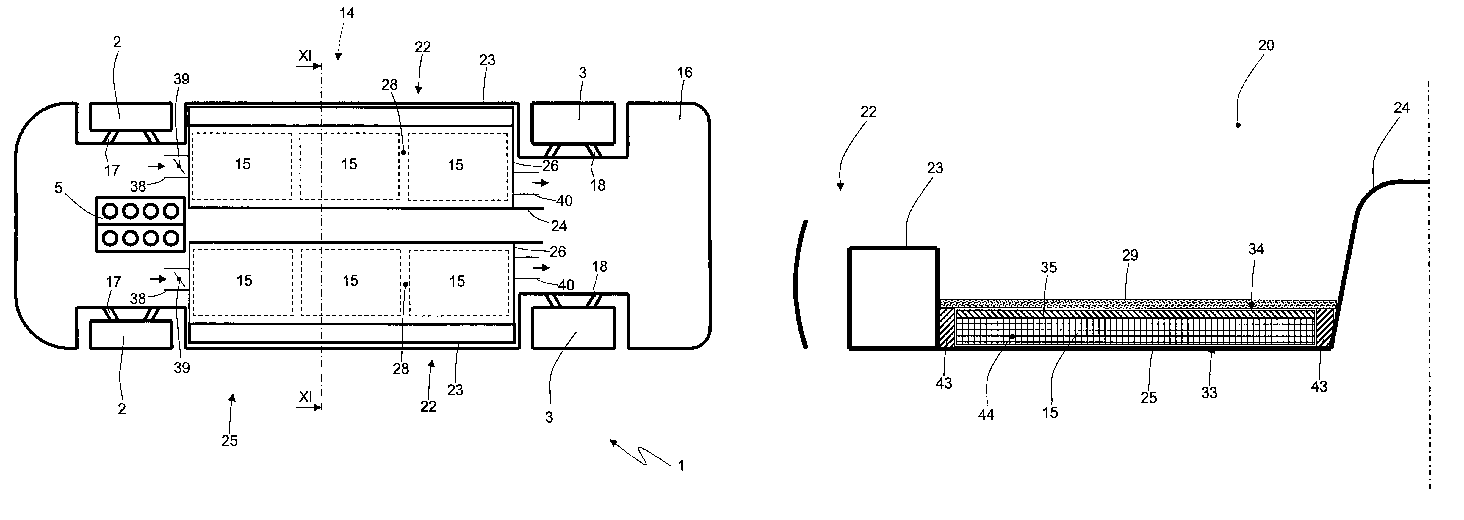
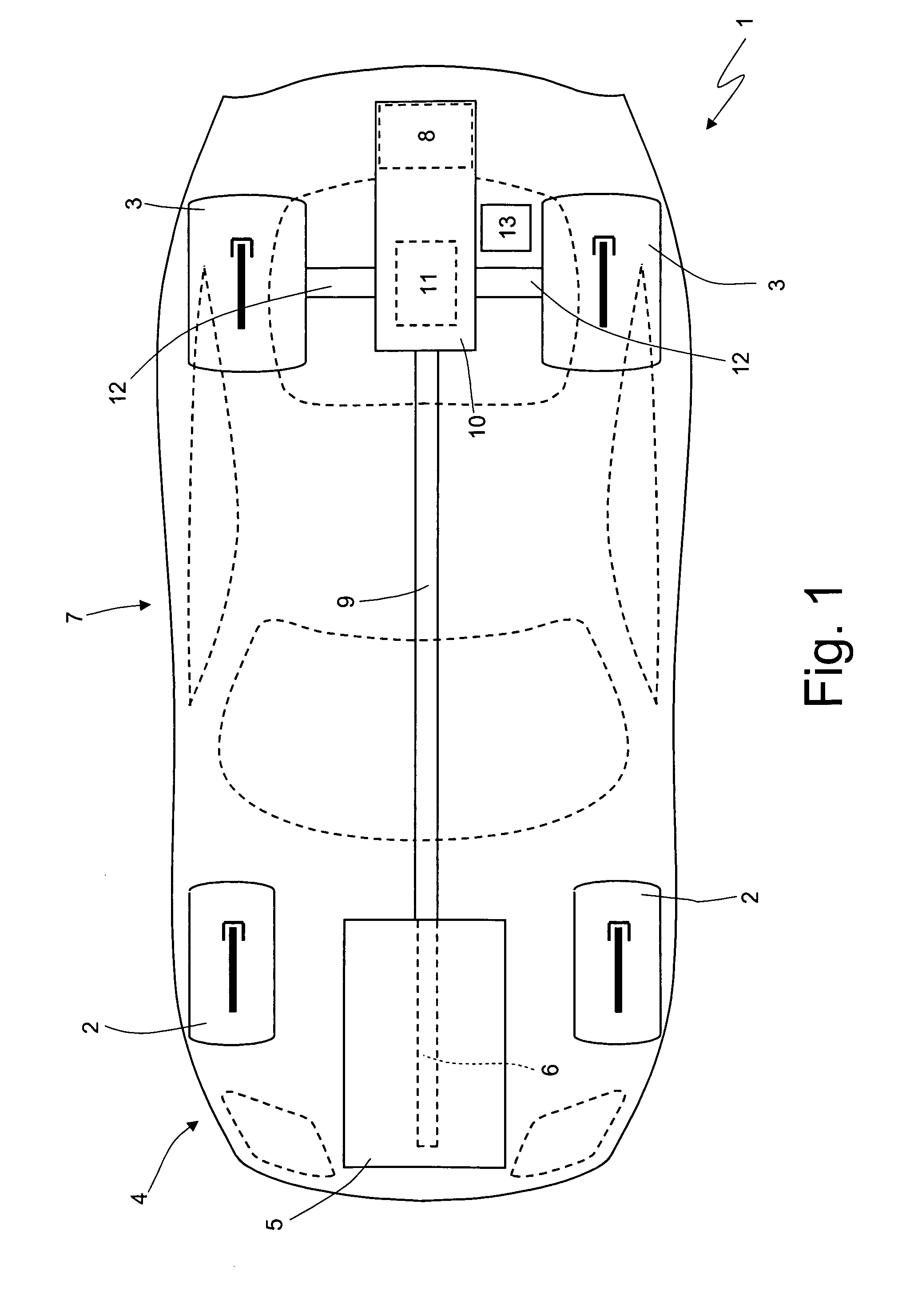
[0012]FIG. 1 is a schematic plan view with parts of a hybrid propulsion vehicle removed for clarity;

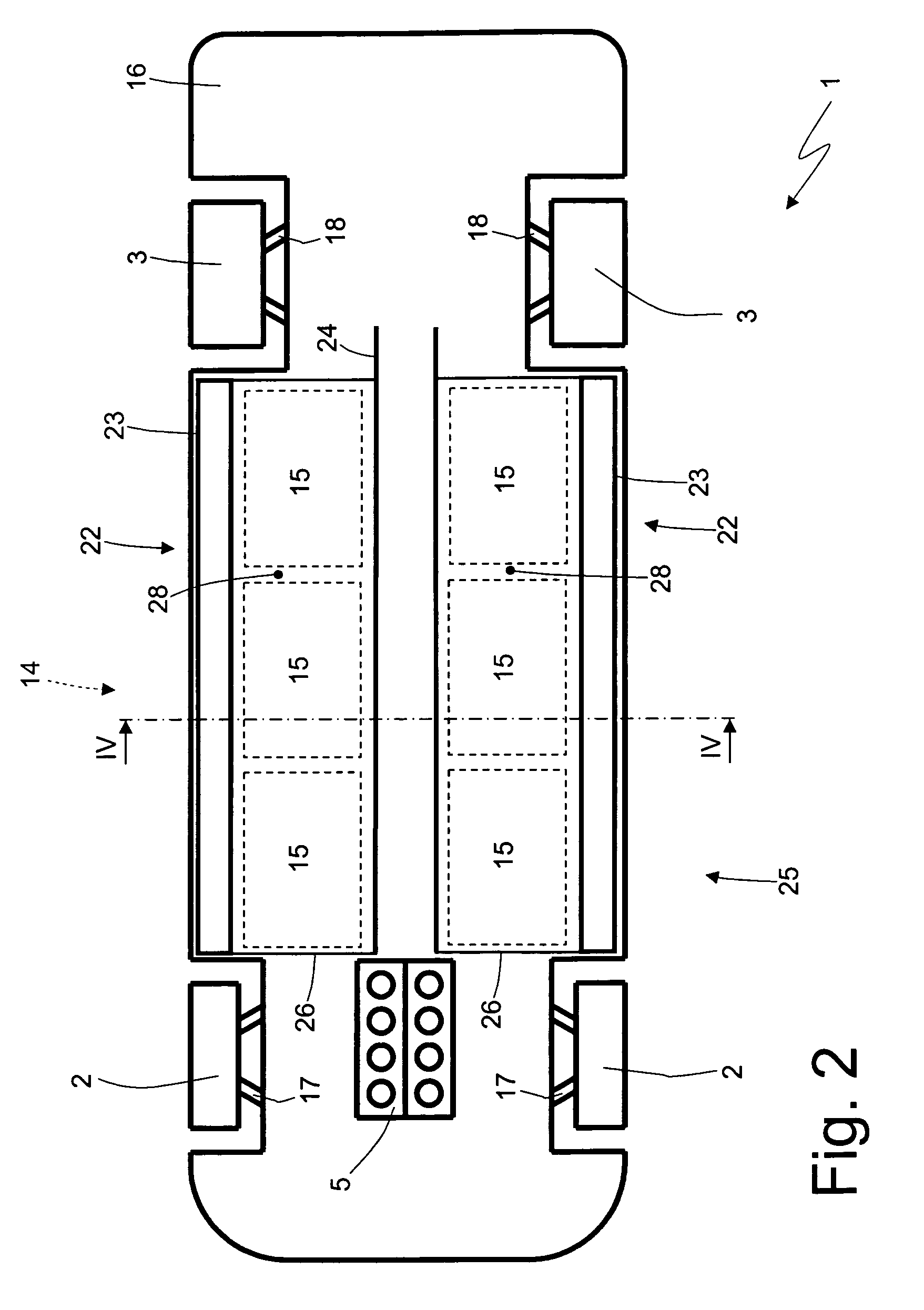
[0013]FIG. 2 is a further schematic plan view with parts of the vehicle in FIG. 1 removed for clarity;

[0014]FIG. 3 a side and schematic view of the vehicle in FIGS. 1 and 2;

[0015]FIG. 4 is a schem...


PUM

PropertyMeasurementUnit
symmetryaaaaaaaaaa
heataaaaaaaaaa
shapeaaaaaaaaaa

Abstract

A method for arranging an accumulating device in proximity of a floor of a vehicle forming a bottom wall of a passenger compartment of the vehicle itself; the accumulating device has a heating base wall which is free from heat insulation, and a non-heating base wall which is parallel and opposite to the heating base wall and is provided with a heat-insulating material layer; and the method provides for the steps of arranging the accumulating device in a seating obtained in proximity of the floor; and implementing the accumulating device with a symmetry allowing the reversal of the accumulating device itself within the seating obtained in proximity of the floor in such a way that the heating base wall may be equally either facing upwards and then towards the passenger compartment or facing downwards and then towards the external environment.

Description

RELATED APPLICATION[0001]This application claims the benefit of priority, under 35 U.S.C. Section 119, to Italian Patent Application Serial No. B02008A 000760, filed on Dec. 18, 2008 and Italian Patent Application Serial No. B02009 A000015, filed Jan. 16, 2009 which are incorporated herein by reference in their entirety.TECHNICAL FIELD[0002]The present invention relates to a method for arranging an electric accumulating device in proximity of a vehicle floor and a hybrid propulsion vehicle.PRIOR ART[0003]A hybrid vehicle comprises an internal combustion engine which transmits the driving torque to the driving wheels by means of a transmission provided with a gearbox, and at least one electric machine which is mechanically connected to the driving wheels. The electric machine is controlled by an electric drive connected to an electric accumulating system typically made of a pack of chemical batteries possibly connected in parallel to one or more super-capacitors.[0004]While the vehic...

Claims


Application Information

Patent Timeline
Patent Type & Authority Patents(United States)
IPC IPC(8): B60K1/04
CPCB62D25/20B60K2001/0438Y10T29/49826B60L15/20B60L2240/423B60L2240/443Y02T10/70Y02T10/72B60L50/40B60L50/16B60L58/21B60L58/26B60L58/27B60L50/66B60L50/64B62D35/02Y02T10/88Y02T10/64Y02T10/7072
Inventor STEFANI, GIOVANNICIMATTI, FRANCOFAVARETTO, FABRIZIO
Owner SPAN FERRARI SPA
Why Eureka
Try Eureka