
Semiconductor device comprising self-aligned contact bars and metal lines with increased via landing regions

a technology of contact bars and metal lines, which is applied in the direction of semiconductor devices, semiconductor/solid-state device details, electrical apparatus, etc., can solve the problems of forming complex logic circuitry, memory devices, and limiting factors of the finally achieved operating speed of complex integrated circuits, and achieve reliable contact of metal lines, reduce bottom critical dimensions, and increase lateral dimensions

Active Publication Date: 2013-03-19
GLOBALFOUNDRIES U S INC
View PDF12 Cites 4 Cited by
  • Summary
  • Abstract
  • Description
  • Claims
  • Application Information

AI Technical Summary

Benefits of technology

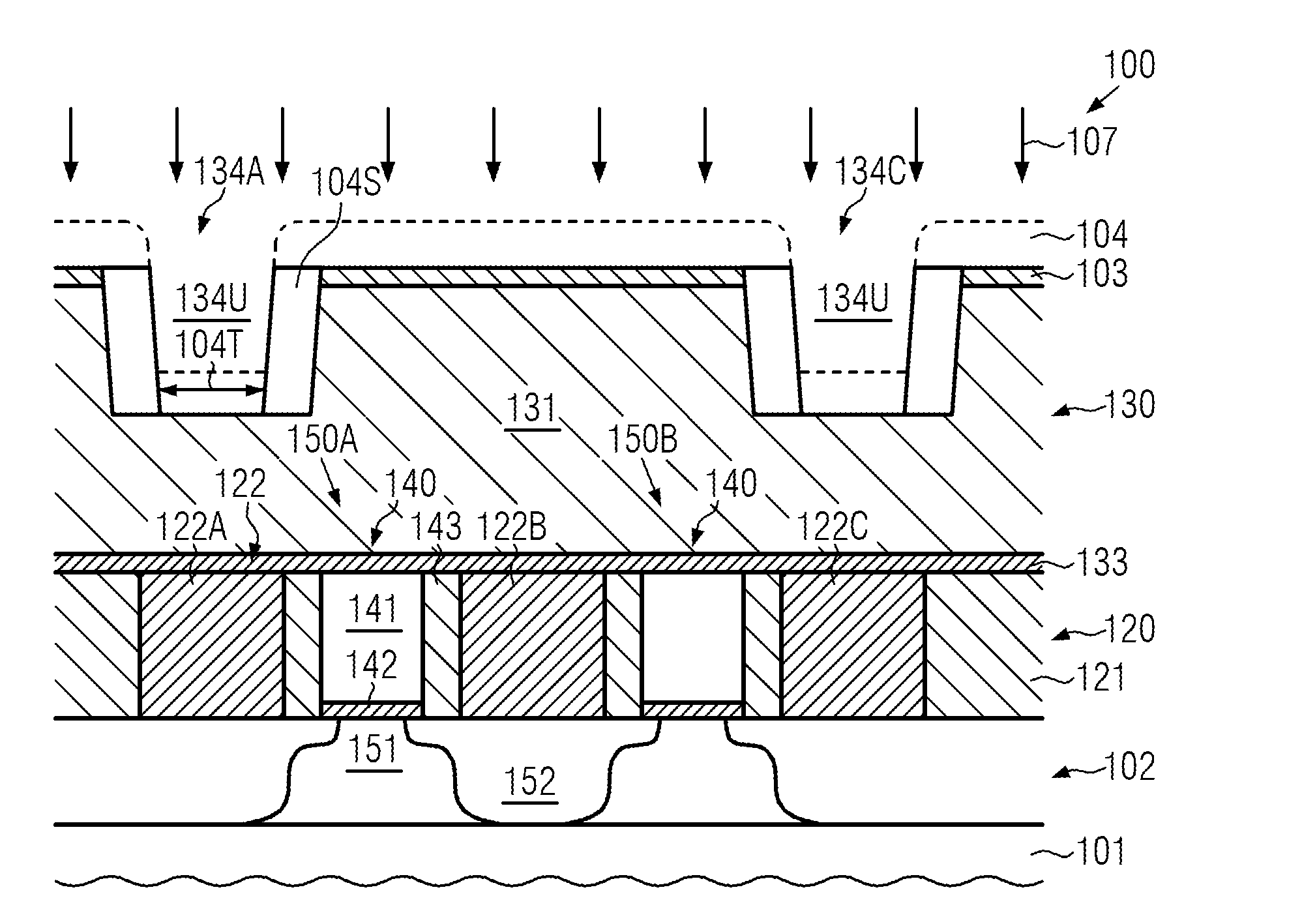
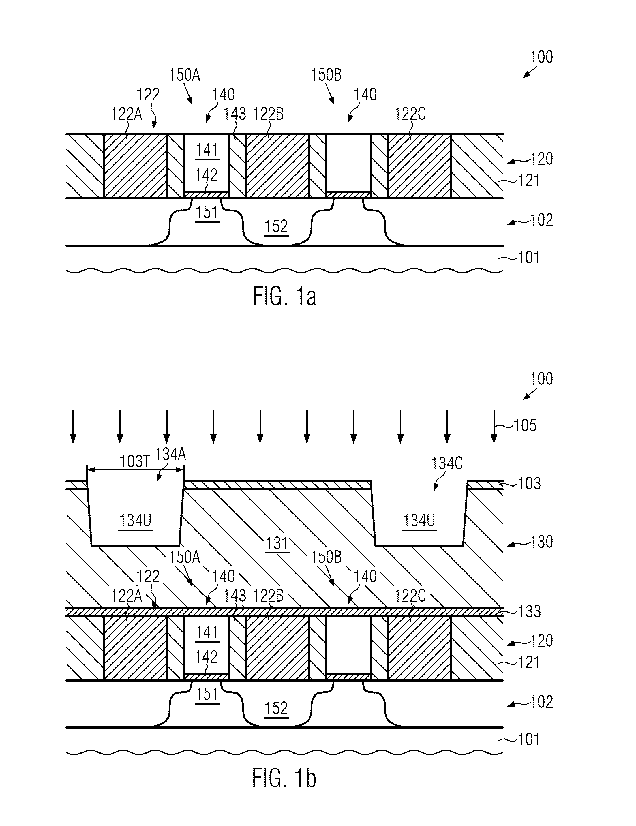
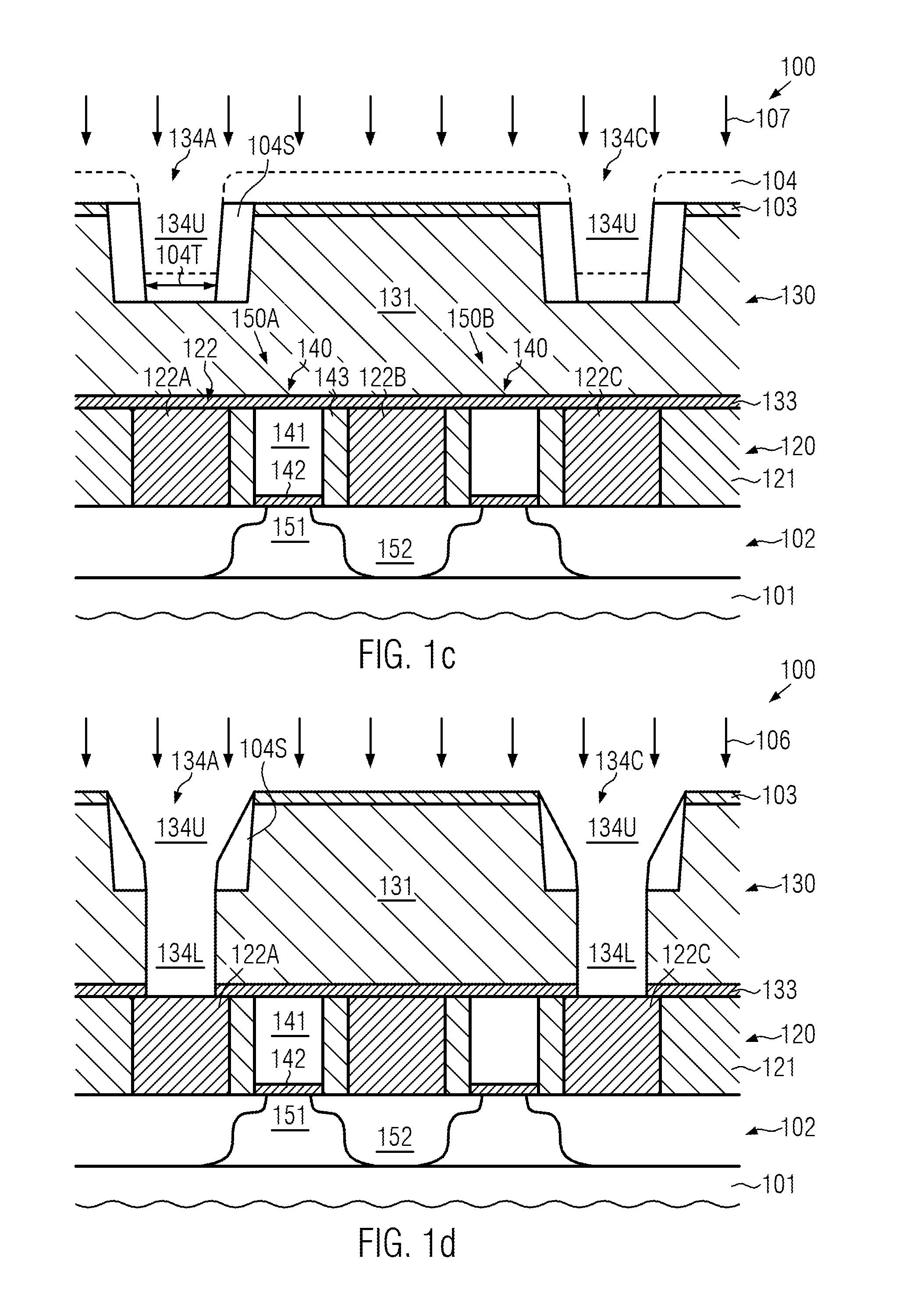
This patent provides techniques for making semiconductor devices with metal lines that can be connected by metal vias. The metal lines have a reduced bottom size to prevent them from being affected by nearby elements, while the top size is increased to ensure better contact with the metal vias. This is achieved by forming a trench with a sacrificial spacer that automatically adjusts the bottom size of the metal line. Overall, this patent enables creating reliable connections between metal lines and vias in advanced semiconductor devices.

Problems solved by technology

On the basis of the field effect transistors, more complex circuit components may be composed, such as inverters and the like, thereby forming complex logic circuitry, memory devices and the like.
Due to the reduced dimensions, the operating speed of the circuit components has been increased with every new device generation, wherein, however, the limiting factor of the finally achieved operating speed of complex integrated circuits is no longer the individual transistor elements but the electrical performance of the complex wiring fabric, which may be formed above the device level including the actual semiconductor-based circuit elements, such as transistors and the like.
On the other hand, applying any etch strategies in which a pronounced tapering is achieved so as to provide a sufficient top critical dimension while also complying with an extremely small bottom critical dimension may result in pronounced patterning-related non-uniformities, thereby contributing to a pronounced yield loss in this manufacturing stage.

Method used


Image

  • Semiconductor device comprising self-aligned contact bars and metal lines with increased via landing regions
  • Semiconductor device comprising self-aligned contact bars and metal lines with increased via landing regions
  • Semiconductor device comprising self-aligned contact bars and metal lines with increased via landing regions

Examples


Embodiment Construction

[0022]Various illustrative embodiments of the invention are described below. In the interest of clarity, not all features of an actual implementation are described in this specification. It will of course be appreciated that in the development of any such actual embodiment, numerous implementation-specific decisions must be made to achieve the developers' specific goals, such as compliance with system-related and business-related constraints, which will vary from one implementation to another. Moreover, it will be appreciated that such a development effort might be complex and time-consuming, but would nevertheless be a routine undertaking for those of ordinary skill in the art having the benefit of this disclosure.

[0023]The present subject matter will now be described with reference to the attached figures. Various structures, systems and devices are schematically depicted in the drawings for purposes of explanation only and so as to not obscure the present disclosure with details ...


PUM


Abstract

When forming metal lines of the metal zero level, a reduced bottom width and an increased top width may be achieved by using appropriate patterning regimes, for instance using a spacer structure after forming an upper trench portion with a top width, or forming the lower portion of the trenches and subsequently applying a further mask and etch regime in which the top width is implemented. In this manner, metal lines connecting to self-aligned contact bars may be provided so as to exhibit a bottom width of 20 nm and less, while the top width may allow reliable contact to any vias of the metallization system.

Description

BACKGROUND OF THE INVENTION[0001]1. Field of the Invention[0002]The present disclosure generally relates to the fabrication of integrated circuits, and, more particularly, to the contact level of a semiconductor device, in which contact areas, such as drain and source regions, are connected to the metallization system of the semiconductor device.[0003]2. Description of the Related Art[0004]In modern integrated circuits, such as microprocessors, storage devices and the like, a very high number of circuit elements, especially transistors, are provided and operated on a restricted chip area. Although immense progress has been made over recent decades with respect to increased performance and reduced feature sizes of the circuit elements, the ongoing demand for enhanced functionality of electronic devices forces semiconductor manufacturers to steadily reduce the dimensions of the circuit elements and to increase the operating speed thereof. The continuing scaling of feature sizes, howev...

Claims


Application Information

Patent Timeline
Patent Type & Authority Patents(United States)
IPC IPC(8): H01L21/4763
CPCH01L21/76808H01L21/76813H01L21/76816H01L23/5226H01L23/5384H01L27/088H01L2924/0002H01L2924/00
Inventor WERNER, THOMASBAARS, PETERFEUSTEL, FRANK
Owner GLOBALFOUNDRIES U S INC
Features
  • Generate Ideas
  • Intellectual Property
  • Life Sciences
  • Materials
  • Tech Scout
  • Unparalleled Data Quality
  • Higher Quality Content
  • 60% Fewer Hallucinations
Learn More