
Gate patterning for AC and DC performance boost

a gate pattern and dc technology, applied in the field of integrated circuits, can solve the problems of increasing the increasing the performance and power degradation of leakage current, increasing the circuit standby power of short transistor gate lengths, etc., to reduce parasitic capacitance, good overlap, and increase the distance of the upper portion

Active Publication Date: 2018-03-20
GLOBALFOUNDRIES U S INC
View PDF1 Cites 0 Cited by
  • Summary
  • Abstract
  • Description
  • Claims
  • Application Information

AI Technical Summary

Benefits of technology

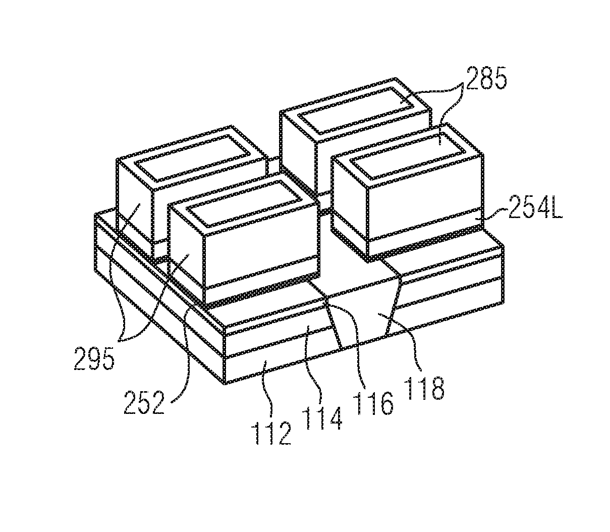
The patent describes a method for improving the performance of MOSFETs or FDSOI FETs by reducing parasitic capacitance without affecting the overlap of the lower gate portion with the source and drain regions in the substrate. This is achieved by creating a cascaded gate profile with a larger distance of the upper portion of the gate to the RSD. The protective layer also acts as an extra mask for the final etch step, reducing the tip-to-tip distance of the formed gate structures and leading to higher integration of the semiconductor device.

Problems solved by technology

Unfortunately, very thin gate insulators have resulted in increased gate leakages or gate-induced leakages, increasing circuit stand-by power for short transistor gate lengths.
Second, a very thin silicon layer creates the transistor channel.
The buried oxide layer also constrains electrons flowing between the source and drain to significantly reduce performance- and power-degrading leakage current.
If the device channel has a thickness of about 20 nm or less, the thickness of the silicon available to form a silicide contact is limited.
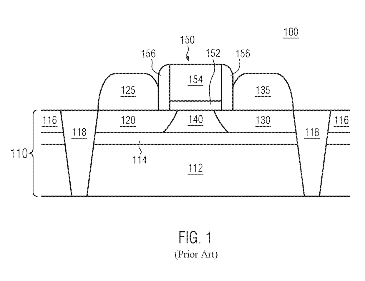
In the currently developed 22 nm FDSOI technology, this parasitic capacitance leads to a trade-off between AC and DC performance.

Method used


Image

  • Gate patterning for AC and DC performance boost
  • Gate patterning for AC and DC performance boost
  • Gate patterning for AC and DC performance boost

Examples


Embodiment Construction

[0022]Various illustrative embodiments of the invention are described below. In the interest of clarity, not all features of an actual implementation are described in this specification. It will of course be appreciated that in the development of any such actual embodiment, numerous implementation-specific decisions must be made to achieve the developers' specific goals, such as compliance with system-related and business-related constraints, which will vary from one implementation to another. Moreover, it will be appreciated that such a development effort might be complex and time-consuming, but would nevertheless be a routine undertaking for those of ordinary skill in the art having the benefit of this disclosure.

[0023]The following embodiments are described in sufficient detail to enable those skilled in the art to make use of the disclosure. It is to be understood that other embodiments would be evident, based on the present disclosure, and that system, structure, process or mec...


PUM


Abstract

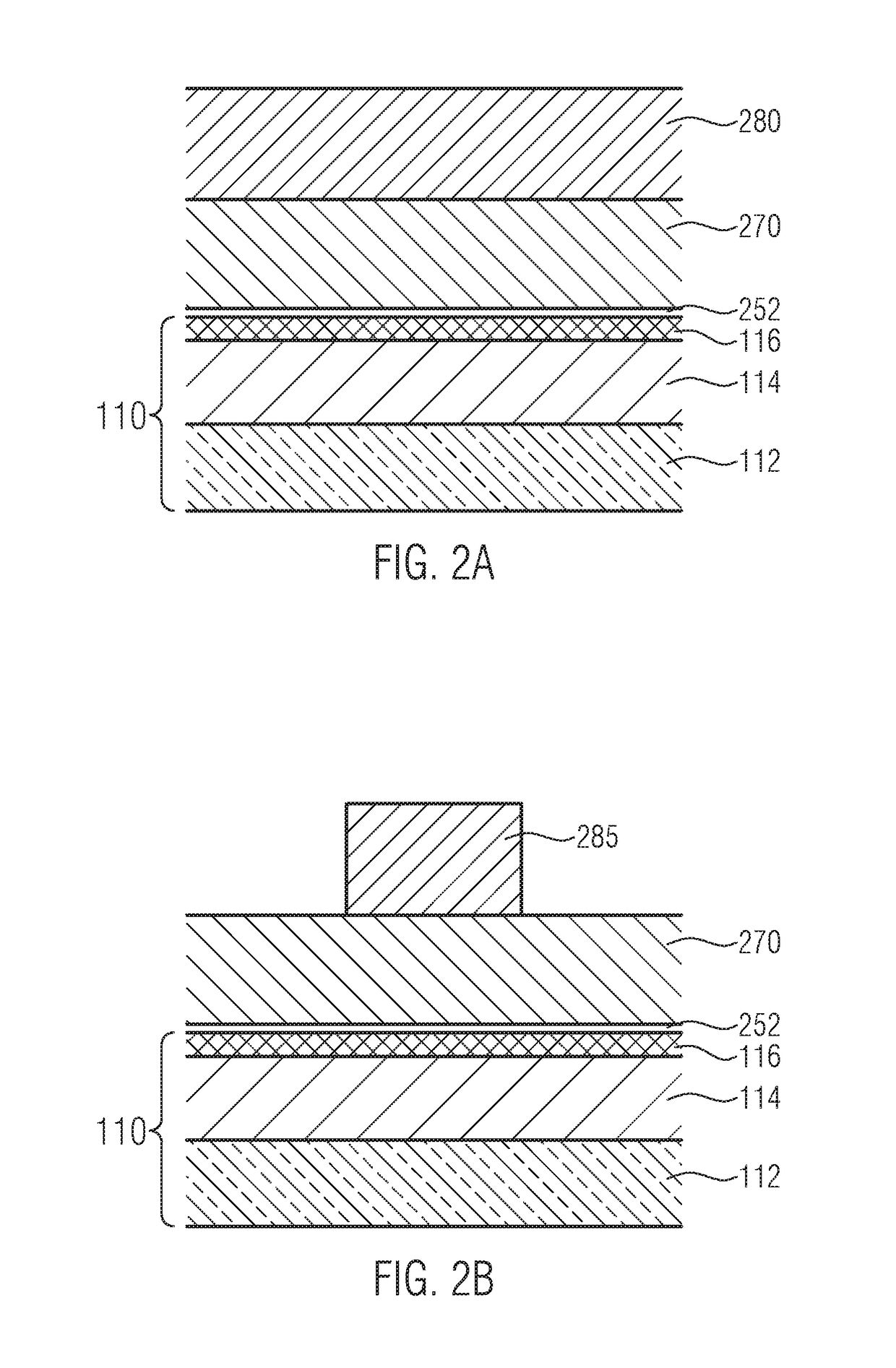
A method to reduce parasitic capacitance in a high-k dielectric metal gate (HKMG) transistor with raised source and drain regions (RSD) is provided including forming a multilayer stack for an HKMG gate on a substrate, the multilayer stack including a gate electrode layer of amorphous silicon or polycrystalline silicon, forming a patterned hard mask above the gate electrode layer, etching partially into the gate electrode layer through the patterned hard mask to define multiple partially etched gate stacks and a partially etching gate electrode layer, forming a conformal protective layer wrapping over the partially etched gate electrode layer and the patterned hard mask, and etching through a remainder of the partially etched gate electrode layer with the conformal protective layer wrapped over the partially etched gate stacks and the patterned hard mask, as well as an HKMG transistor resulting therefrom.

Description

BACKGROUND OF THE INVENTION1. Field of the Invention[0001]Generally, the subject matter disclosed herein relates to integrated circuits, and, more particularly, to transistor devices, in particular field effect transistor devices, with raised source and drain.2. Description of the Related Art[0002]As integrated circuits become more and more integrated, the sizes of the corresponding circuit elements, such as transistors, have to shrink accordingly. As a consequence, field effect transistors (FETs) with very thin gate dielectric layers using a high-k dielectric have been developed to mitigate short channel effects. Unfortunately, very thin gate insulators have resulted in increased gate leakages or gate-induced leakages, increasing circuit stand-by power for short transistor gate lengths. As a remedy, sub-threshold leakage and other short channel effects have been controlled and reduced by thinning the device channel layer.[0003]Fully depleted (FD) devices have been formed in ultrath...

Claims


Application Information

Patent Timeline
Patent Type & Authority Patents(United States)
IPC IPC(8): H01L21/302H01L29/66H01L29/417H01L29/51H01L29/786H01L29/06H01L21/306H01L21/308
CPCH01L29/51H01L21/3085H01L21/30604H01L29/786H01L29/41783H01L29/6656H01L29/66484H01L29/0649H01L21/84H01L27/1203H01L21/32139H01L29/42376H01L29/66628
Inventor SMITH, ELLIOT JOHN
Owner GLOBALFOUNDRIES U S INC
Features
  • Generate Ideas
  • Intellectual Property
  • Life Sciences
  • Materials
  • Tech Scout
  • Unparalleled Data Quality
  • Higher Quality Content
  • 60% Fewer Hallucinations
Learn More