Communication device, communication system, image presentation method, and program

a communication system and image technology, applied in the field of communication, can solve the problems of users not familiar with computer operations, complicated procedures requiring relatively high skills, and inability to improve the operation, and achieve the effect of easy uploading of captured images

Active Publication Date: 2013-03-19
PANASONIC INTELLECTUAL PROPERTY CORP OF AMERICA
View PDF25 Cites 36 Cited by
  • Summary
  • Abstract
  • Description
  • Claims
  • Application Information

AI Technical Summary

Benefits of technology

[0017]The communication device according to the aspect of the present invention is capable of facilitating various settings for a display device such as a TV providing information regarding the object (the communication device). For example, the communication device enables a user to easily upload images captured by the user to a server and view the images from the server on the TV, without any complicated procedures.

Problems solved by technology

Therefore, the operability is not improved.
However, such procedures requiring relatively high skills are complicated and bothersome for middle-aged and elderly people and general women.
Users not familiar with computer operations find difficult to enjoy the services.
The problem in operability has been examined to be improved, but the improved techniques are not different from the conventional computer operation methods.
The operability is not significantly improved.

Method used


Image

  • Communication device, communication system, image presentation method, and program
  • Communication device, communication system, image presentation method, and program
  • Communication device, communication system, image presentation method, and program

Examples


first embodiment

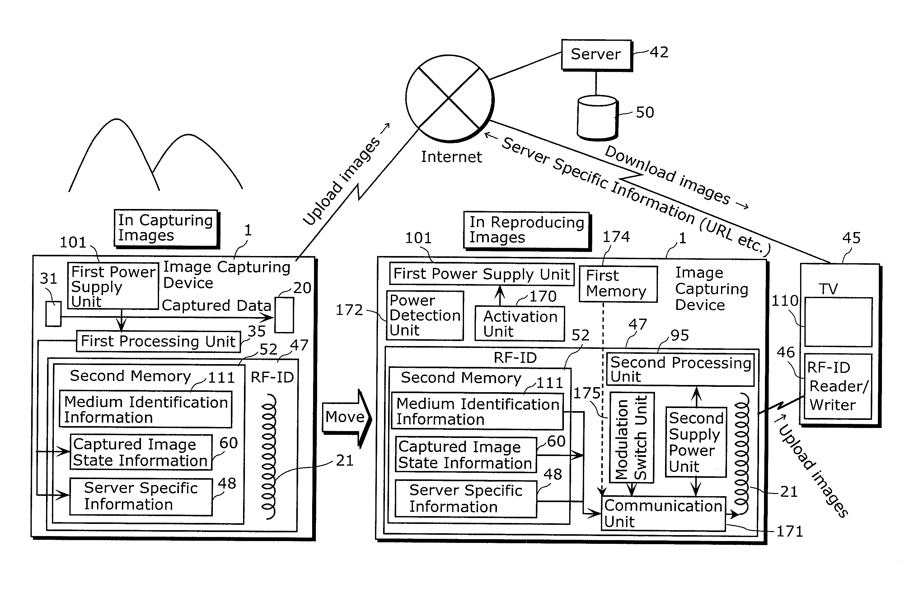
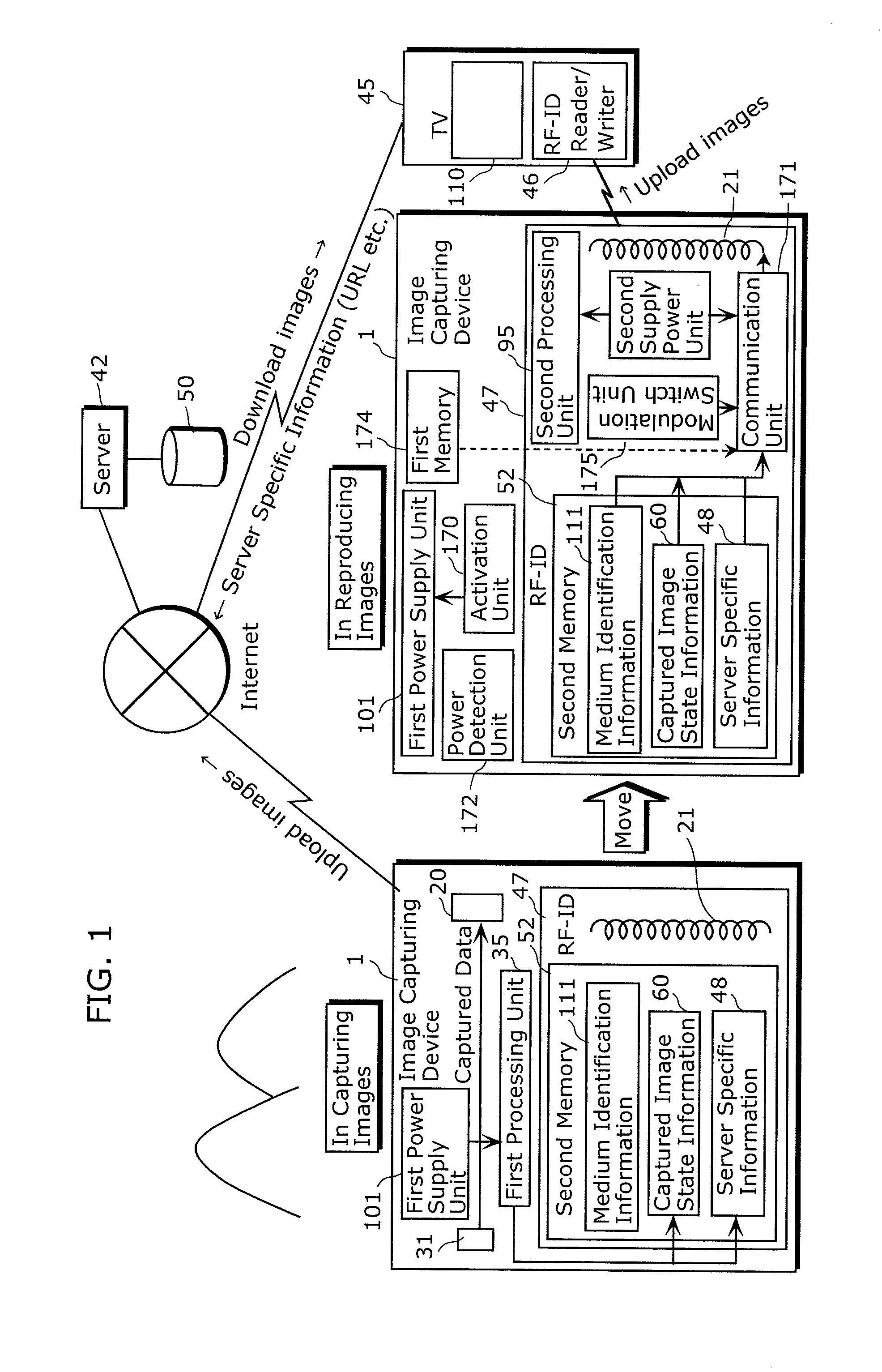
[0309]The first embodiment according to the present invention is described below. FIG. 1 is a schematic diagram of the first embodiment of the present invention. Here, a communication system including an image capturing device (camera) 1, a TV 45, and a server 42 is illustrated. In FIG. 1, the image capturing device 1 capturing images is illustrated on a left-hand side, while the image capturing device 1 reproducing the captured images is illustrated on a right-hand side.

[0310]The image capturing device 1 is an example of the communication device according to the aspect of the present invention. Here, the image capturing device 1 is implemented as a digital camera. For units used in capturing images, the image capturing device 1 includes a first power supply unit 101, a video processing unit 31, a first antenna 20, a first processing unit 35, a second memory 52, and a RF-ID antenna (second antenna) 21. The second memory 52 holds medium identification information 111, captured image ...

second embodiment

[0496]The following describes the second embodiment of the present invention. In the second embodiment, actual operations of the communication system are described. In the communication system, images captured by a camera are uploaded to a server, and then downloaded by a simple operation to a TV to be displayed. The whole configuration of the communication system according to the second embodiment is the same as that of the communication system according to the first embodiment.

[0497]FIGS. 40A to 40E are flowcharts of processing performed by a camera (the image capturing device 1) to upload photographs (images). First, the camera captures images (Step S5101). Then, the captured images are stored into the third memory (Step S5102). Then, the camera updates information stored in the second memory (Step S5103). The second memory updating process will be described later. Next, the camera determines whether or not the communication unit is connectable to the Internet (Step S5104). If co...

third embodiment

[0609]The third embodiment according to the present invention is described below.

[0610]First, the third embodiment is explained in summary. FIG. 48 is a schematic block diagram of an electronic catalog display system according to the third embodiment. The electronic catalog display system according to the third embodiment includes an electronic catalog server information input device 500, an electronic catalog notification card 502, the TV 45, and an electronic catalog server 506. The electronic catalog server information input device 500 includes a RF-ID writer 501. The electronic catalog notification card 502 includes a RF-ID unit 47. The TV 45 includes a RF-ID reader 504 and a network communication unit 509. The electronic catalog server 506 includes an electronic catalog database 507 and a customer attribute database 508.

[0611]The electronic catalog server information input device 500 writes electronic catalog server information from the RF-ID writer 501 to the RF-ID unit 47 att...


PUM


Abstract

A communication device that can simplify various settings of a display device, such as a TV, that provides information regarding an object (communication device) is provided. An image capturing device (1) has a RF-ID unit (47) for performing proximity wireless communication with a RF-ID reader / writer (46) connected via an infrared communication path to a TV (45). The image capturing device (1) includes: an antenna (21) for the proximity wireless communication; a data receiving unit (105) receiving an input signal from the RF-ID reader / writer (46); a nonvolatile second memory (52) storing at least UID (75) and an execution program (116); and a data transmission unit (108) transmitting the UID (75) and the execution program (116) to the RF-ID reader / writer (46) via the antenna (21) according to the input signal. The UID (75) is used to identify the communication device, and the execution program (116) is executed by the TV (45) with reference to the UID (75). The transmitted UID (75) and execution program (116) are transferred to the TV (45) via the RF-ID reader / writer (46).

Description

TECHNICAL FIELD[0001]The present invention relates to a communication device or the like performing proximity wireless communication with a device (apparatus) having a reader.BACKGROUND ART[0002]In recent years, services provided via the Internet have been increasingly prevalent. As servers manage text information, images, videos, and the like created by users as well as news, weather forecast, movie information, and other contents created by companies, services for supplying these contents any time via the Internet have also been rapidly increased.[0003]One of the services is photograph sharing service. A user can upload photographs taken by the user himself / herself to a server, and later view the photographed images any time by accessing the server from a personal computer or the like via the Internet.[0004]In order to upload photographed images to a server, products have recently been developed to facilitate the uploading procedure. Digital cameras, memory cards, and the like hav...

Claims


Application Information

Patent Timeline
Patent Type & Authority Patents(United States)
IPC IPC(8): H04N5/76H04N7/16
CPCH04N1/00007H04N1/00244H04N1/00079H04N1/00291H04N1/00342H04N1/00899H04N1/00901H04N5/225H04N5/23203H04N7/163H04N21/4182H04N21/43615H04N21/4432H04W88/04G06K7/10297H04N1/00214H04N1/00029H04N1/32106H04N2101/00H04N2201/0041H04N2201/0053H04N2201/0055H04N2201/0084H04N2201/3204H04N2201/3205H04N2201/3273H04N2201/3278H04N23/66H04N23/00
Inventor IKEDA, YOICHIOSHIMA, MITSUAKIYAMAOKA, MASARUMUKAI, TSUTOMUSATO, TAKAHIROFUCHIGAMI, IKUOTEZUKA, TADANORIOHTSUBO, SHOHJIMATSUSHITA, YOSUKE
Owner PANASONIC INTELLECTUAL PROPERTY CORP OF AMERICA
Why Eureka
Try Eureka