Secondary-emitter sensor position indicator

a technology of position indicator and emitter, which is applied in the field of secondary emitter sensor position indicator, can solve problems such as sensor out-of-position errors

Active Publication Date: 2013-03-19
JPMORGAN CHASE BANK NA
View PDF238 Cites 575 Cited by
  • Summary
  • Abstract
  • Description
  • Claims
  • Application Information

AI Technical Summary

Benefits of technology

[0011]In various embodiments, a first secondary emitter is located in a first position relative to the primary emitters. A second secondary emitter is located in a second position relative to the primary emitters. The attachment assembly, in a sensor mis-positioned condition, positions the secondary emitters relative to the tissue site so that the sensor signal is negligibly responsive to the first secondary emitter and at least partially responsive to the second secondary emitter. The attachment assembly, in a sensor-off condition, may position the secondary emitters relative to the tissue site so that the sensor signal is at least partially responsive to the first secondary emitter and the second secondary emitter. A third secondary emitter may be located in a third position relative to the primary emitters. The attachment assembly, in a sensor-on condition, positions the secondary emitters relative to the tissue site so that the sensor signal is negligibly responsive to the first and second secondary emitters and at least partially responsive to the third secondary emitter. The attachment assembly, in a sensor over-positioned condition, positions the secondary emitters relative to the tissue site so that the sensor signal is negligibly responsive to the first, second and third secondary emitters. A processor portion of the physiological monitor may operate on the sensor signal so as to determine the position of a finger relative to the sensor according to at least multiple ones of a sensor-on condition, a sensor out-of-position condition, a sensor off condition and a sensor mis-positioned condition. A display portion of the physiological monitor may be responsive to the processor determination of sensor and finger position so as to graphically depict the position of a finger relative to the sensor. An alarm portion of the physiological monitor may be responsive to the processor determination of sensor and finger position so as to audibly indicate the position of a finger relative to the sensor.

Problems solved by technology

Problems arise if a pulse oximeter or other blood parameter monitor is connected to an optical sensor that is not properly positioned on a tissue site or becomes partially or completely dislodged from a patient, a sensor out-of-position condition including sensor-off and sensor mis-position conditions.
Sensor out-of-position errors are serious because a blood parameter monitor may still display a normal measurement, potentially leading to critical missed events, such as an oxygen desaturation.

Method used


Image

  • Secondary-emitter sensor position indicator
  • Secondary-emitter sensor position indicator
  • Secondary-emitter sensor position indicator

Examples


Embodiment Construction

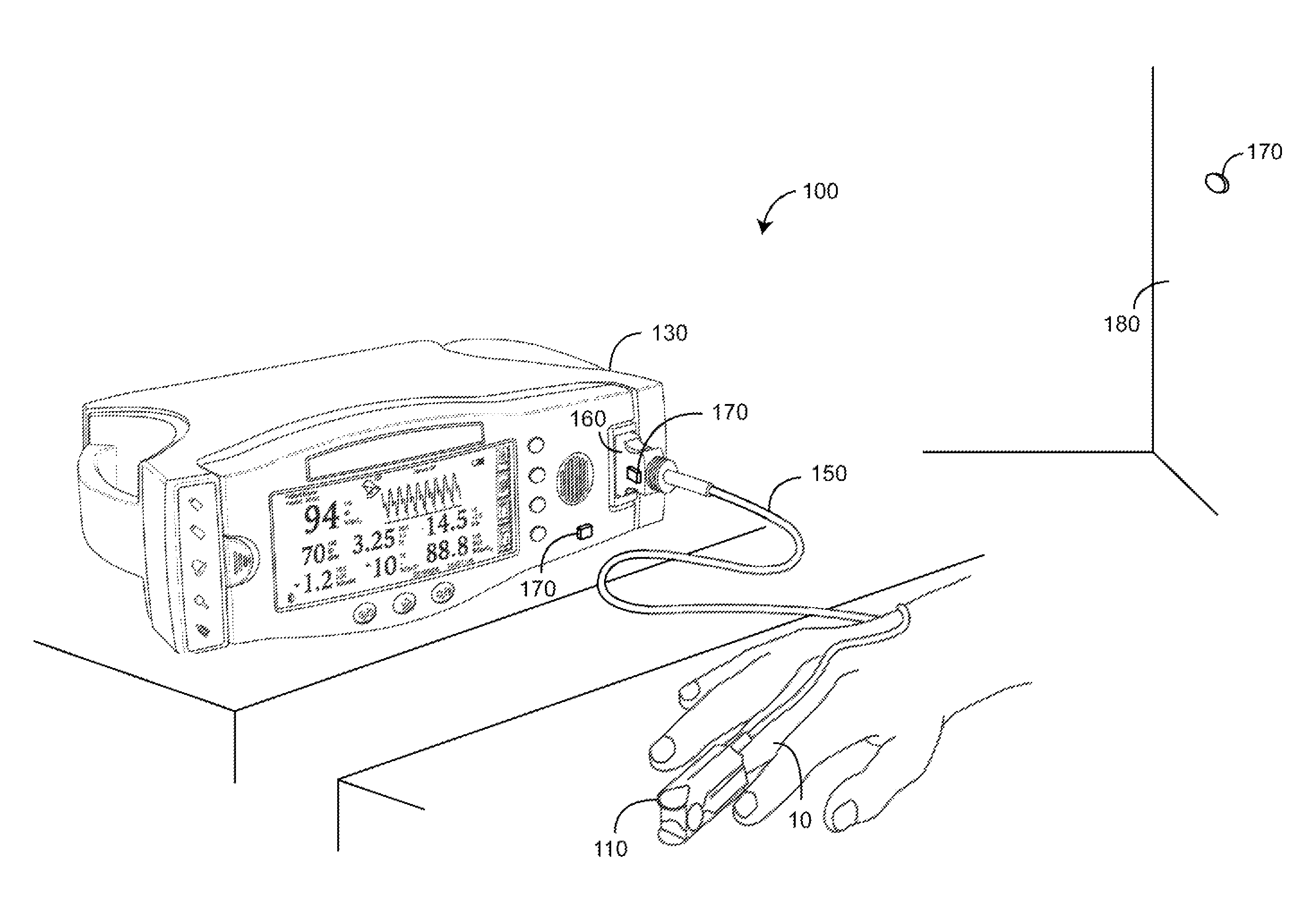
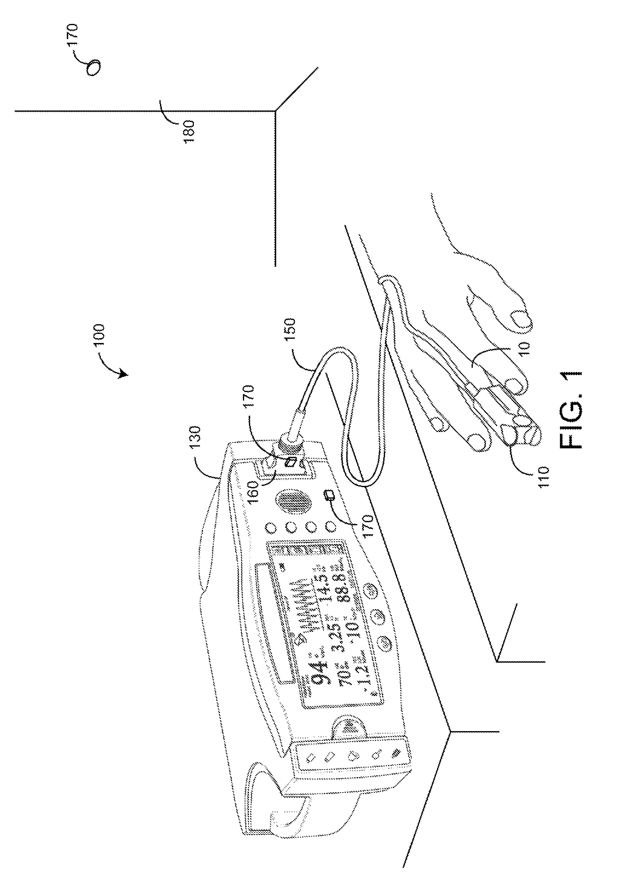
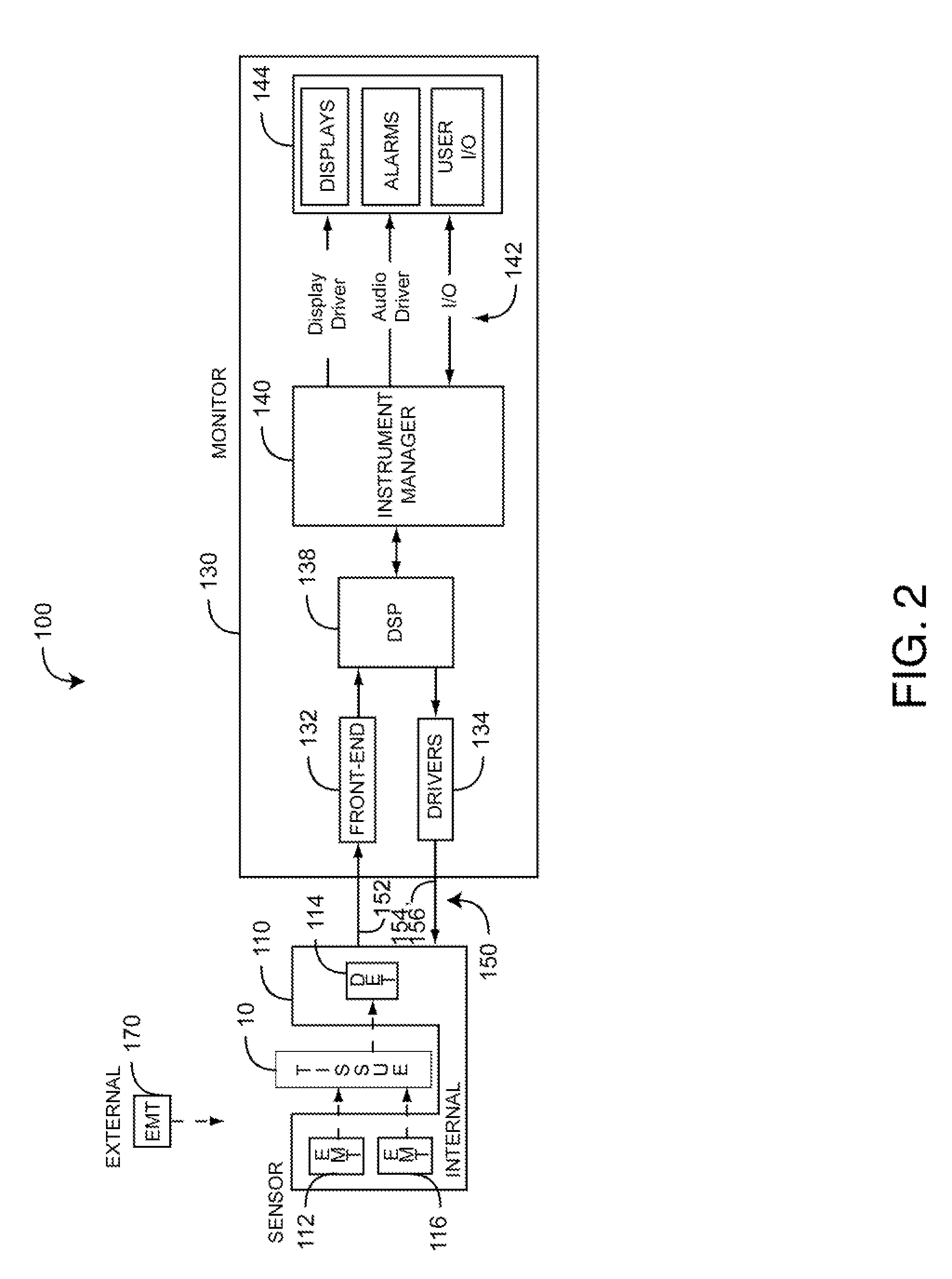
[0021]FIGS. 1-2 illustrate a physiological measurement system 100 which measures blood constituents and related parameters, such as oxygen saturation, pulse rate, perfusion index (PI), pleth variability index (PVI™), HbCO, HbMet and Hbt, to name a few. The physiological measurement system 100 includes an optical sensor 110 applied to a tissue site 10, a monitor 130 and a cable 150 that physically and electrically connects the sensor 110 to the monitor 130. Advantageously, the physiological measurement system 100 also utilizes a sensor position indicator responsive to improper placement of the sensor 110 on a finger or other tissue site 10, as described in detail below.

[0022]As shown in FIGS. 1-2, the patient monitor 130 communicates with the sensor 110 to receive one or more intensity signals indicative of one or more physiological parameters. Drivers 134 convert digital control signals into analog drive signals 154 capable of driving primary emitters 112 that transmit optical radia...


PUM


Abstract

A secondary-emitter sensor position indicator has primary emitters that transmit light having primary wavelengths and at least one secondary emitter that transmits light having at least one secondary wavelength. A detector outputs a sensor signal in response to received light. An attachment assembly, in a sensor-on condition, positions the emitters and detector relative to a tissue site so that the sensor signal is substantially responsive to the primary wavelength light after attenuation by pulsatile blood flow within the tissue site and is negligibly responsive to the secondary wavelength light. The attachment assembly, in a sensor out-of-position condition, positions the secondary emitter relative to the tissue site so that the sensor signal is at least partially responsive to the secondary wavelength.

Description

CROSS-REFERENCE TO RELATED APPLICATIONS[0001]The present application claims priority benefit under 35 U.S.C. §119(e) to U.S. Provisional Patent Application Ser. No. 61 / 104,890, filed Oct. 13, 2008, titled Secondary-Emitter Sensor Position Indicator, hereby incorporated by reference herein.BACKGROUND OF THE INVENTION[0002]Pulse oximetry is a technique that utilizes a noninvasive sensor to determine a person's oxygen status. An optical sensor used in pulse oximetry has light emitting diodes (LEDs) that transmit optical radiation of red and infrared wavelengths into a tissue site. A detector in the sensor responds to the intensity of the optical radiation after attenuation by pulsatile arterial blood flowing within the tissue site. Based on this response, a processor determines measurements for SpO2 and pulse rate among other parameters. Pulse oximeters capable of reading through motion induced noise are available from Masimo Corporation (“Masimo”) of Irvine, Calif. Moreover, portable ...

Claims


Application Information

Patent Timeline
Patent Type & Authority Patents(United States)
IPC IPC(8): A61B5/00
CPCA61B5/061A61B5/6838A61B5/6826A61B5/14552
Inventor KIANI, MASSI JOE E.
Owner JPMORGAN CHASE BANK NA
Why Eureka
Try Eureka