Method and system for integrated reservoir and surface facility networks simulations

a technology of reservoir and surface facility, applied in the field of method and system for integrated reservoir and surface facility network simulation, can solve the problems of inability to meet the needs of drilling, inefficient and difficult maintenance, lack of flexibility

Inactive Publication Date: 2013-03-19
SCHLUMBERGER TECH CORP
View PDF16 Cites 19 Cited by
  • Summary
  • Abstract
  • Description
  • Claims
  • Application Information

AI Technical Summary

Problems solved by technology

Although an implicit: surface / subsurface coupling might provide better convergence when solving the non-linear system of equations, it suffers from a lack of flexibility when it comes to software choice.12 Furthermore, coupling several reservoir models to a shared surface facility is not feasible implicitly without amalgamating these models into a single grid (with a large number of grid blocks), which would be inefficient and difficult to maintain.11,13
The main disadvantage of an iteratively lagged scheme relative to a fully implicit scheme that includes all the derivatives is that the reservoir simulator may require more Newton iterations to converge its time step.
In some circumstances omitting these derivatives may compromise the convergence of the time step.
The iteratively lagged coupling scheme; however, is not well suited for cases where multiple reservoir models are coupled to the surface model.
An iteratively lagged coupling scheme would require the reservoir models to be tightly synchronised to take the same time steps (the minimum of the time step sizes of all the models), which may slow the simulation process considerably.
This is less accurate than the iteratively lagged scheme and may result in a degree of inconsistency between the reservoir and network solutions.

Method used


Image

  • Method and system for integrated reservoir and surface facility networks simulations
  • Method and system for integrated reservoir and surface facility networks simulations
  • Method and system for integrated reservoir and surface facility networks simulations

Examples


examples

[0093]We present two example applications that illustrate the features described above. The first example describes multiple reservoirs coupled to a common surface network, with global constraints applied via network chokes. The second example illustrates component delumping and gas re-injection between three reservoirs with different fluid models.

example i

Coupling Multiple Reservoirs to a Network

[0094]Three sub-sea reservoirs are connected to a common production network. FIG. 7 shows a schematic diagram of the network, which couples to the reservoir models at the well tubing heads. Each reservoir contains four production wells. The produced fluids from each well flow along separate sea-bed flow-lines to a manifold, where they co-mingle. Each reservoir has a single manifold, and a separate riser to bring the fluid to a common production platform. At the platform the fluid from the three risers is co-mingled and transported to shore along an export pipeline. Each reservoir has the same black oil fluid description; the oil is initially undersaturated with a dissolved gas concentration Rs=1.5 Mscf / stb. Initially only two of the reservoirs, Reservoirs A and B, are on stream; Reservoir C comes on stream eight months later.

[0095]The total deliverability is limited by a pressure constraint of 500 psia at the on-shore export node. But the tot...

example ii

Component Delumping and Gas Re-injection

[0099]Three reservoirs with different fluid models are coupled through global production and injection constraints. Each reservoir has seven producers. Reservoirs A and B have three water injectors each. Reservoir C has four gas injectors. As in Example I, each reservoir has a single manifold. The produced fluid from manifolds MAN-A, MAN-B and MAN-C is gathered at the GATHER point where gas is separated, some of which is re-injected in Reservoir C. In this example we focus on some compositional aspects of the controller. Therefore, for the sake of clarity, no workovers are performed on any of the wells during the run.

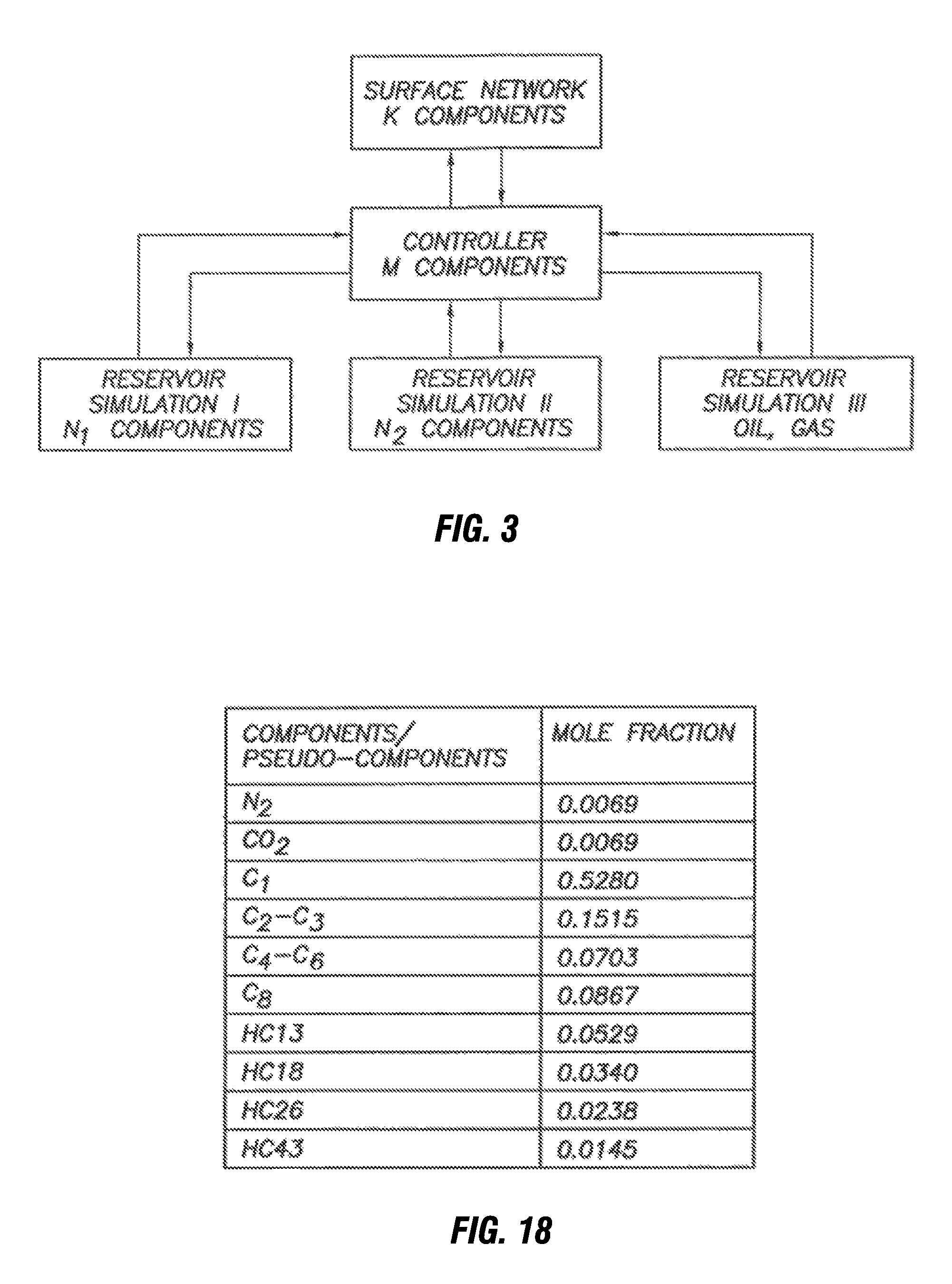
[0100]The three reservoirs are isothermal. The fluid models for the three reservoirs are the following:[0101]Reservoir A is a CVD black oil model (initial GOR=1.85 Mscf / stb) with a mixture of live oil and wet gas; the same model that was used in the black oil validation example (see FIG. 4 and FIG. 18). The reservoir temperature i...


PUM


Abstract

A method includes initiating a first reservoir simulation on a first simulator for a first set of physical parameters of a first reservoir. The first reservoir simulator uses a first set of components for a compositional reservoir model. A second reservoir simulation is initiated on a second simulator. A network simulation is initiated on a network simulator to model a network for coupling the first reservoir and the second reservoir to a surface facility. The network simulator uses a second set of components for a compositional network model. The method further includes translating each of a first hydrocarbon fluid stream of the first reservoir simulator and a second hydrocarbon fluid stream of the second reservoir simulator to a common fluid model. Further, network balancing is initiated among the simulators at a corresponding point in each controller time step.

Description

BACKGROUND OF THE INVENTION[0001]1. Field of the Invention[0002]The recently published literature shows the need for a comprehensive integrated modeling solution for coupling multiple reservoir simulations and surface facility networks.1-8 This need is emphasized by recent deepwater oil and gas field development where, typically, wells from different reservoirs flow through pipelines to a shared surface facility platform before being transported by a pipeline to the sale point. Surface / subsurface coupling involves several issues including:[0003]The coupling mode of the surface and subsurface models: explicit or implicit. This has previously been described for the case of a single reservoir simulation coupled to a surface network model.9,10 [0004]The application of global production and injection / re-injection constraints to a coupled system of multiple reservoirs.11 [0005]The use of different PVT models (black oil models and compositional models having different sets of pseudo-compon...

Claims


Application Information

Patent Timeline
Patent Type & Authority Patents(United States)
IPC IPC(8): G06G7/50E21B49/00G06FG06F17/50
CPCE21B41/00E21B49/00G06F17/5009G06F2217/80G06F2217/06G06F2217/16G06F2111/04G06F2111/10G06F2119/08G06F30/20G06F30/28
Inventor GHORAYEB, KASSEMHOLMES, JONATHANTORRENS, RICHARDGREWAL, BALRAJ
Owner SCHLUMBERGER TECH CORP
Why Eureka
Try Eureka