

Illumination apparatus and display apparatus
a technology of display apparatus and illumination apparatus, which is applied in the direction of discharge tube luminescnet screens, lighting and heating apparatus, instruments, etc., can solve the problem of becoming more difficult to illuminate the entire panel uniformly with high luminance as the display becomes larger, and achieve excellent display quality and reduce view angle dependency
- Summary
- Abstract
- Description
- Claims
- Application Information
AI Technical Summary
Benefits of technology
Problems solved by technology
Method used
Image

Examples
first embodiment
[0026]Hereinafter, an illumination apparatus as an embodiment of the present invention will be described.
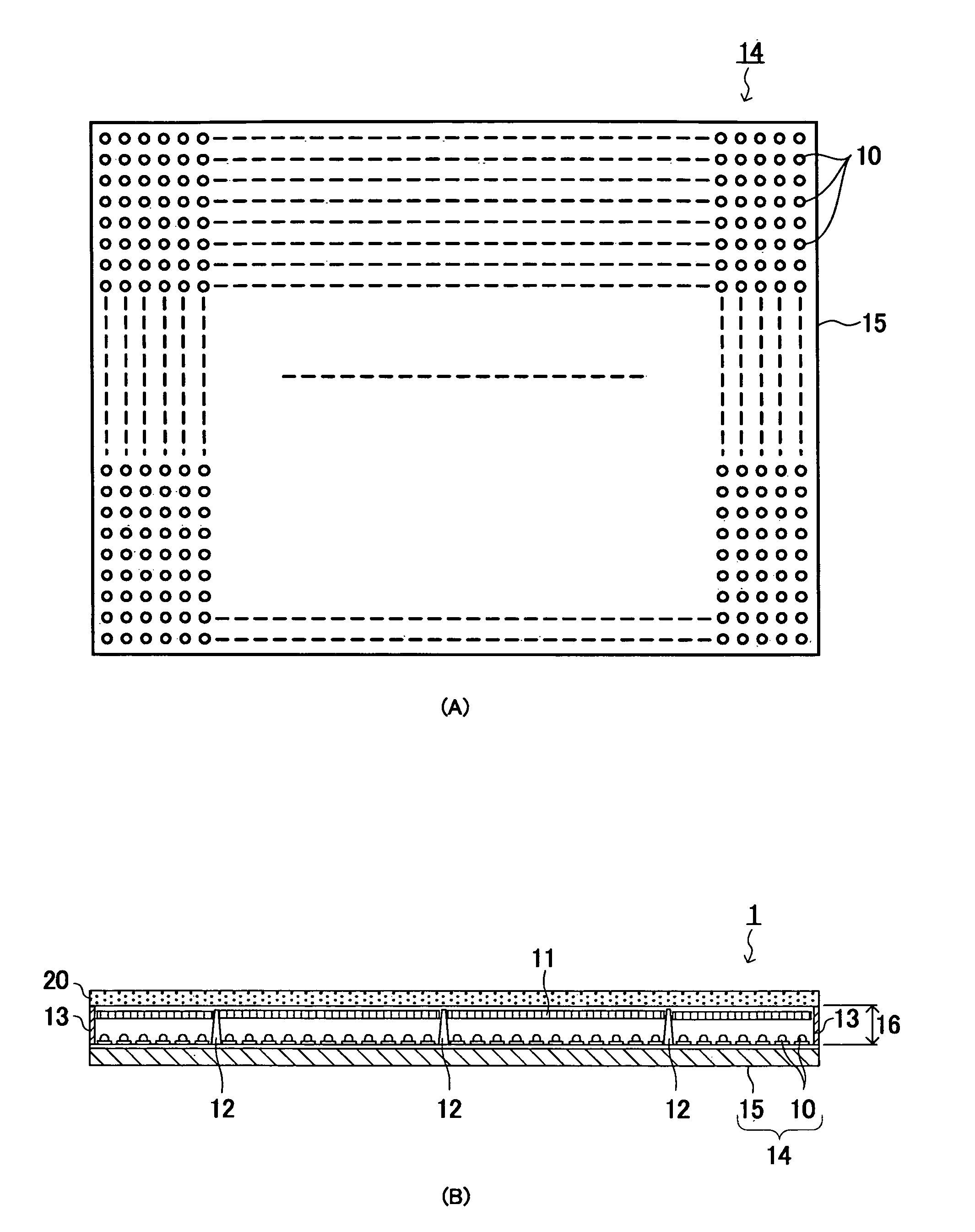
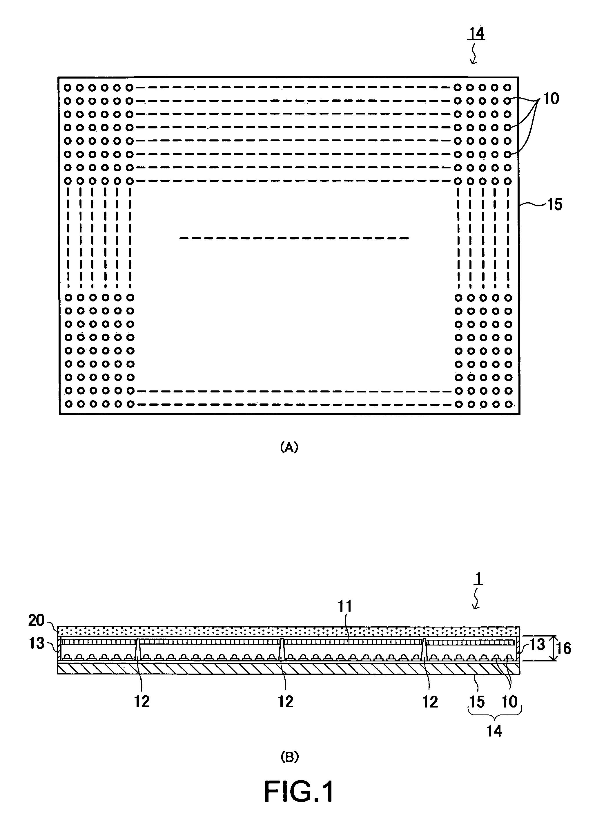
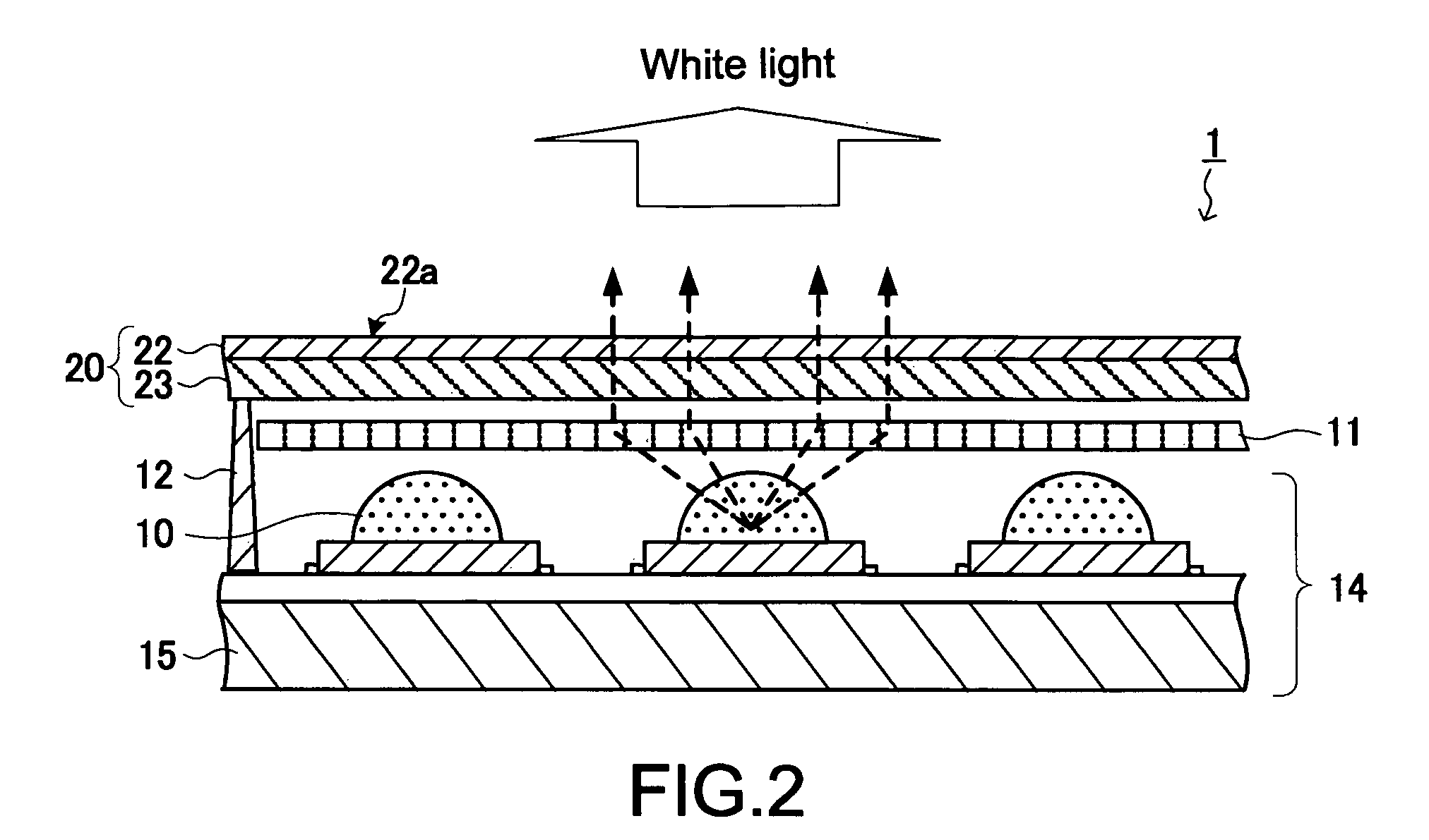
[0027]FIG. 1(A) is a schematic plan view of a light-emitting device substrate 14 partially constituting the illumination apparatus 1, and FIG. 1(B) is a schematic cross-sectional diagram of the illumination apparatus 1. FIG. 2 is a partially-enlarged cross-sectional diagram of the illumination apparatus 1.
[0028]As shown in FIG. 1, the illumination apparatus 1 includes the light-emitting device substrate 14 whose planar shape is a rectangle, reflective plates 13, a phosphor sheet 20 whose planar shape is a rectangle, and a light beam control device 11 as a light beam control portion that is interposed between the light-emitting device substrate 14 and the phosphor sheet 20. The light-emitting device substrate 14 and the phosphor sheet 20 are apart by about 1 to 30 mm, and a gap 16 therebetween is supported by a plurality of support columns 12 and the reflective plates 13. The refl...
example 1
[0040]FIG. 5 is a cross-sectional diagram showing a structure of the illumination apparatus 1 that uses a Fresnel lens 31 as the light beam control device 11, and FIG. 6 is a side view showing a positional relationship between the Fresnel lens 31 and the light-emitting diode 10 and a plan view of the Fresnel lens 31. The Fresnel lens 31 is obtained by annularly cutting out a convex surface of a plano-convex lens to obtain serrate rings, and continuously and concentrically arranging the rings. Each of the Fresnel lenses 31 is positioned such that an optical center thereof coincides with an optical axis of the corresponding one of the light-emitting diodes 10. A shape of the concentric rings of the Fresnel lens 31 is designed such that emitted light from the light-emitting diodes 10 is bent in the vertical or approximately-vertical direction with respect to the light-emitting surface 22a of the phosphor layer 22 to thus enter the phosphor layer 22. With this structure, light that obli...
example 2
[0042]FIG. 8 is a cross-sectional diagram showing a structure of the illumination apparatus 1 that uses prisms 33 and 34 as the light beam control device 11, and FIG. 9 is a side view showing a positional relationship between the prisms 33 and 34 and the light-emitting diode 10 and plan views of the prisms 33 and 34. The prisms 33 and 34 are planar prisms having periodical curved surfaces in which peaks and valleys are continuously formed in a uniaxial direction. The prisms 33 and 34 overlap each other in a direction in which axes thereof become orthogonal. The periodical curved surfaces of the prisms 33 and 34 are designed such that emitted light from the light-emitting diodes 10 is bent in the vertical or approximately-vertical direction with respect to the light-emitting surface 22a of the phosphor layer 22 to thus enter the phosphor layer 22. With this structure, light that obliquely enters the surface of the phosphor layer 22 is lessened, and the view angle dependency of the ch...
PUM
| Property | Measurement | Unit |
|---|---|---|
| structures | aaaaa | aaaaa |
| luminance | aaaaa | aaaaa |
| thickness | aaaaa | aaaaa |
Abstract
Description
Claims
Application Information