
Exercise resistance system

a resistance system and exercise technology, applied in the field of exercise resistance systems, can solve the problems of inconvenient storage, inconvenient use, and inability to carry or store weights alone, and achieve the effect of quick and easy adjustment, quick and easy adjustment of resistance levels

Inactive Publication Date: 2013-03-26
WILKINSON WILLIAM T +3
View PDF16 Cites 39 Cited by
  • Summary
  • Abstract
  • Description
  • Claims
  • Application Information

AI Technical Summary

Benefits of technology

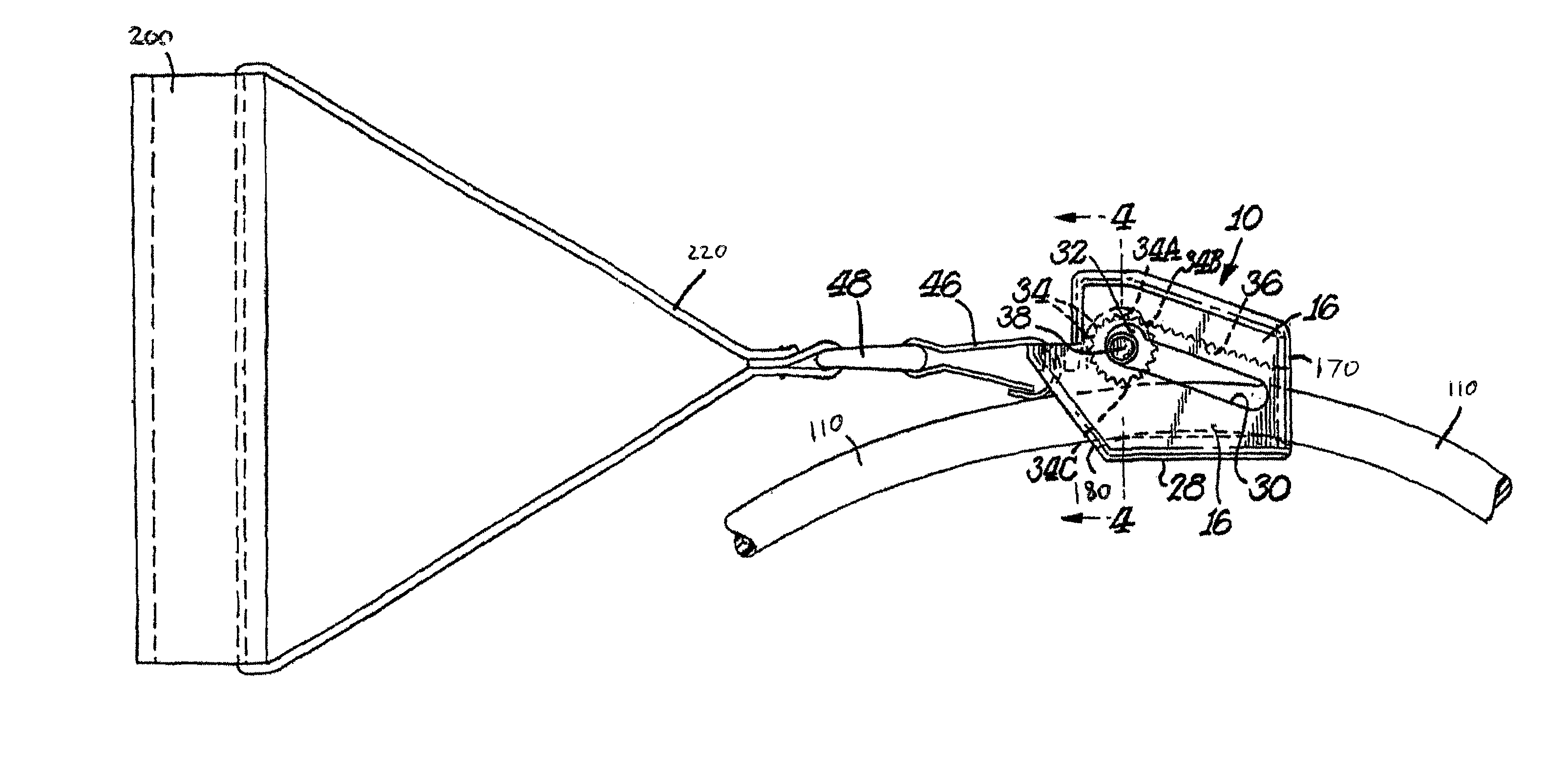
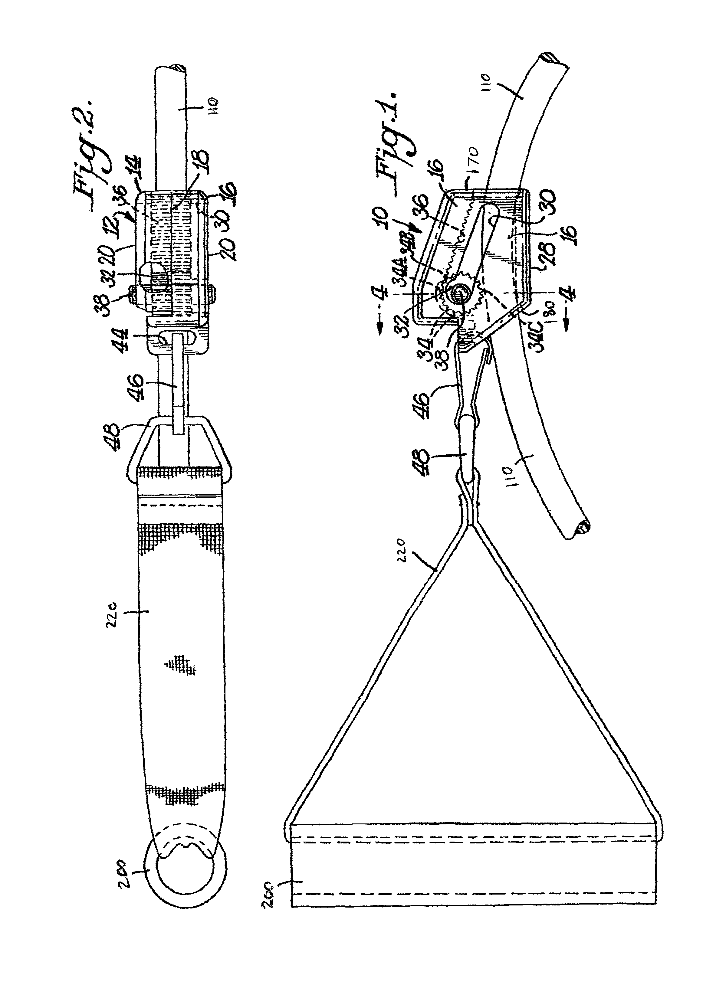
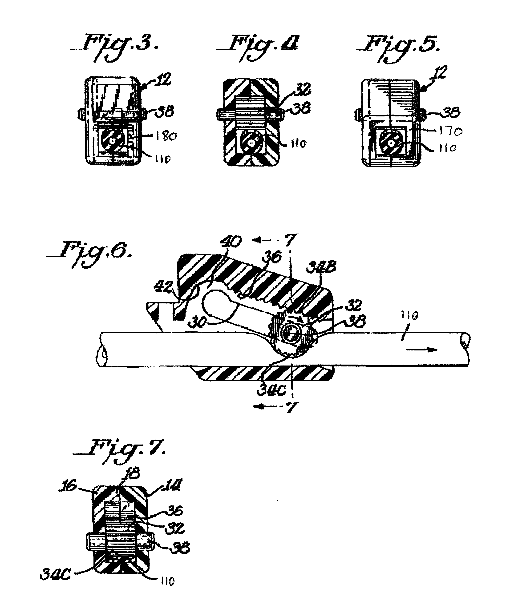
The present invention provides a resistance exercise device that allows for quick and easy adjustment of the resistance level using elastic resistance cords or flat bands. The device includes a length quick adjustment device that can be easily secured at various points along the length of the elastic resistance cords or flat bands to change their usable length. The resistance provided by the elastic resistance cords or flat bands can be adjusted quickly and easily to perform various types of resistance exercise. The device also allows for the creation of unique exercise programs utilizing elastic resistance cords or flat bands for different movements / exercises in a workout program.

Problems solved by technology

However, each form has limitations.
Free weights are generally more expensive, heavy, bulky, and non compact.
Due to their heavy and bulky nature, weights alone are not very portable or easy to store.
Further, adjusting the level of resistance by adding weights or changing to different weights is often time consuming and difficult.
Additionally, adjusting a user's range of motion when utilizing weights is often difficult.
Elastic resistance cords or flat bands also have limitations.
Elastic resistance cords and flat bands are limited because they are generally of a uniform length and strength.
This process is time consuming and expensive.
Thus, elastic resistance cords or flat bands are limited, in that a user cannot easily adjust the strength of resistance or the range of motion.
The limitations in the current state of the art utilizing resistance bands are easily seen in products currently in the marketplace.
However, the means of attaching the resistance cords to the handle and adjusting the resistance cords (a post) has clear limitations in that the resistance cords are not firmly secured to the handle, and the resistance cords easily become dislodged from the handle post.
The inability to adequately secure the resistance cord to the handle not only reduces the effectiveness of the workout, but also creates a potential safety hazard if the cord should inadvertently dislodge from the handle in a workout.
Even with the spherical member in place in the tapered passage, the spherical member is easily dislodged thereby reducing its effectiveness in securing the resilient member.
Additionally, resistance is derived only by pulling two handles in opposite directions, and does not contain a means to attach the resistance bands to another structure thus limiting the number and types of exercises that may be performed.
However, the platform is large and bulky preventing a user from easily transporting the exercise system.
The depressed surface does not create an evenly flat surface thus increasing the risk that the user will sustain an ankle injury when stepping onto the surface of the platform.

Method used


Image

  • Exercise resistance system
  • Exercise resistance system
  • Exercise resistance system

Examples


Embodiment Construction

Combination of More than One Resistance Type

[0053]The present invention is a combination of one or more types of resistance. The invention combines aspects of one or more varied types of exercise including but not limited to a combination of weights, elastic resistance cords or flat bands, springs, coils, flex rods, gyroscopes, magnetic resistance, pneumatic resistance, hydraulic resistance, friction brake resistance, and the weight of a user's own body. The invention is any device that uses one or more types of resistance, but preferably combines two types of resistance. The level of resistance provided by each type of exercise may be fixed or adjustable.

[0054]In a preferred embodiment of the invention, elastic resistance cords, flat bands or springs are used in combination with weights such as dumbbells, bars, or barbells. In this embodiment, resistance may be obtained through elastic or spring resistance, weights, or a combination of these types of resistance to form a new “hybri...


PUM


Abstract

The present invention provides for an improved exercise resistance system to conduct numerous total body exercises. An adjustable elastic resistance cord or flat band may be combined with weights, or each type of resistance may be used alone, in order to vary the means of creating resistance during exercise. The length of the elastic resistance cord or flat band may be adjusted by means of a slip free, length quick adjustment device. The elastic resistance cord or flat band may be passed through the length quick adjustment device which may be secured at various points along the length of the elastic resistance cord or flat band, to change its effective usable length and thus change the level of strength, and range of motion. The length quick adjustment device may be secured by pulling an elastic resistance cord or flat band in one direction, and released by pulling the elastic resistance cord or flat band in the opposite direction.One end of the elastic resistance cord or flat band is attached to any hand engagement structure, preferably a cord handle / grip, a dumbbell handle / grip, a bar, or a glove. The other end of the elastic resistance cord or flat band is secured to any anchor structure, preferably a movable structure, such as a flat board, pad, aerobic step, workout bench, or TV interactive exercise structure.

Description

BACKGROUND OF THE INVENTION[0001]Exercise equipment may provide resistance against muscle movement by a user through various means. The force of gravity provides resistance to users of free weights such as ankle weights, wrist weights, weight vests, dumbbells, and barbells. Free weights may be created by incorporating various forms of metal, water or sand. Some types of exercise equipment also utilize the force of gravity to provide resistance through the transfer of force through cables to weights positioned with the apparatus. Other types of resistance may be created through the use of hydraulic cylinders, springs, and flexible rods. Resistance may also be created with the use of a pressure screw in conjunction with a friction brake. A user's own body weight may provide the necessary resistance to conduct exercise.[0002]Equipment may also utilize elastic resistance cords or flat bands, which stretch and elongate under pressure, to provide the necessary resistance to a user when co...

Claims


Application Information

Patent Timeline
Patent Type & Authority Patents(United States)
IPC IPC(8): A63B21/02
CPCA63B21/00069A63B21/0442A63B21/0552A63B21/0557A63B21/143A63B21/1438A63B21/1469A63B21/1484A63B23/0355F16G11/106A63B21/0726A63B2225/09A63B21/1457A63B21/4015A63B21/4019A63B21/4029A63B21/4035A63B21/4043
Inventor WILKINSON, WILLIAM T.KENNEDY, ROBERTMCGRATH, PAULFERNANDEZ
Owner WILKINSON WILLIAM T
Learn More