
Rotational intravascular ultrasound probe with an active spinning element

an intravascular ultrasound and active technology, applied in the field of rotational intravascular ultrasound probes with active spinning elements, can solve the problems of inability to adopt rotational technology, reduced penetration depth and increased echoes, and increased echoes, so as to facilitate more accurate diagnosis of medical conditions, improve image quality, and reduce cost

Active Publication Date: 2013-03-26
VOLCANO CORP
View PDF16 Cites 25 Cited by
  • Summary
  • Abstract
  • Description
  • Claims
  • Application Information

AI Technical Summary

Benefits of technology

[0007]The present invention provides the enabling technology allowing advanced transducer technology to be introduced into a rotational IVUS catheter. This in turn will provide improved image quality and support advanced signal processing to facilitate more accurate diagnosis of the medical condition within the vessel. All of this can be achieved in a cost-effective way, possibly at a lower cost than the conventional technology.
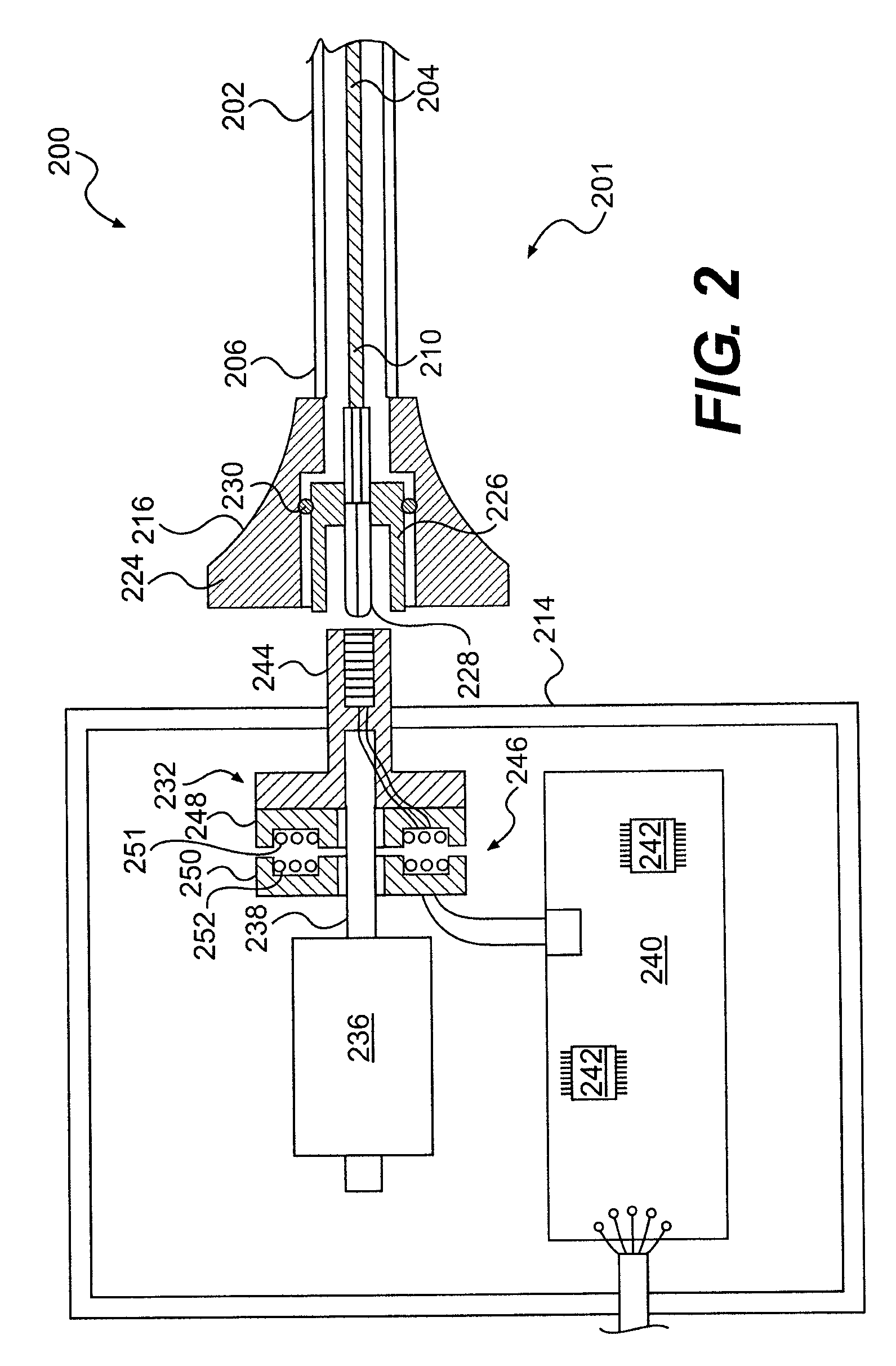
[0008]Embodiments of an intravascular ultrasound probe are disclosed herein. The probe has features for utilizing an advanced transducer technology on a rotating transducer shaft. In particular, the probe accommodates the transmission of the multitude of signals across the boundary between the rotary and stationary components of the probe required to support an advanced transducer technology. These advanced transducer technologies offer the potential for increased bandwidth, improved beam profiles, better signal to noise ratio, reduced manufacturing costs, advanced tissue characterization algorithms, and other desirable features. Furthermore, the inclusion of electronic components on the spinning side of the probe can be highly advantageous in terms of preserving maximum signal to noise ratio and signal fidelity, along with other performance benefits.

Problems solved by technology

In general terms, a higher frequency of operation provides better resolution and a smaller catheter, but at the expense of reduced depth of penetration and increased echoes from the blood (making the image more difficult to interpret).
PMUT and CMUT transducers may provide improved image quality over that provided by the conventional piezoelectric transducer, but these technologies have not been adopted for rotational IVUS applications due to the larger number of electrical leads they require, among other factors.

Method used


Image

  • Rotational intravascular ultrasound probe with an active spinning element
  • Rotational intravascular ultrasound probe with an active spinning element
  • Rotational intravascular ultrasound probe with an active spinning element

Examples


Embodiment Construction

[0018]Turning to the figures, representative illustrations of rotational intravascular ultrasound (IVUS) probes, some of which include active spinning elements, are shown therein. An active spinning element can increase the number of signal paths available for the operation of the transducer so that advanced transducer technologies, such as PMUT (Piezoelectric Micromachined Ultrasonic Transducer) and CMUT (Capacitive Micromachined Ultrasonic Transducer), can be utilized with a rotational IVUS probe. In addition, an active spinning element can include active electronics on the rotary side of the probe.

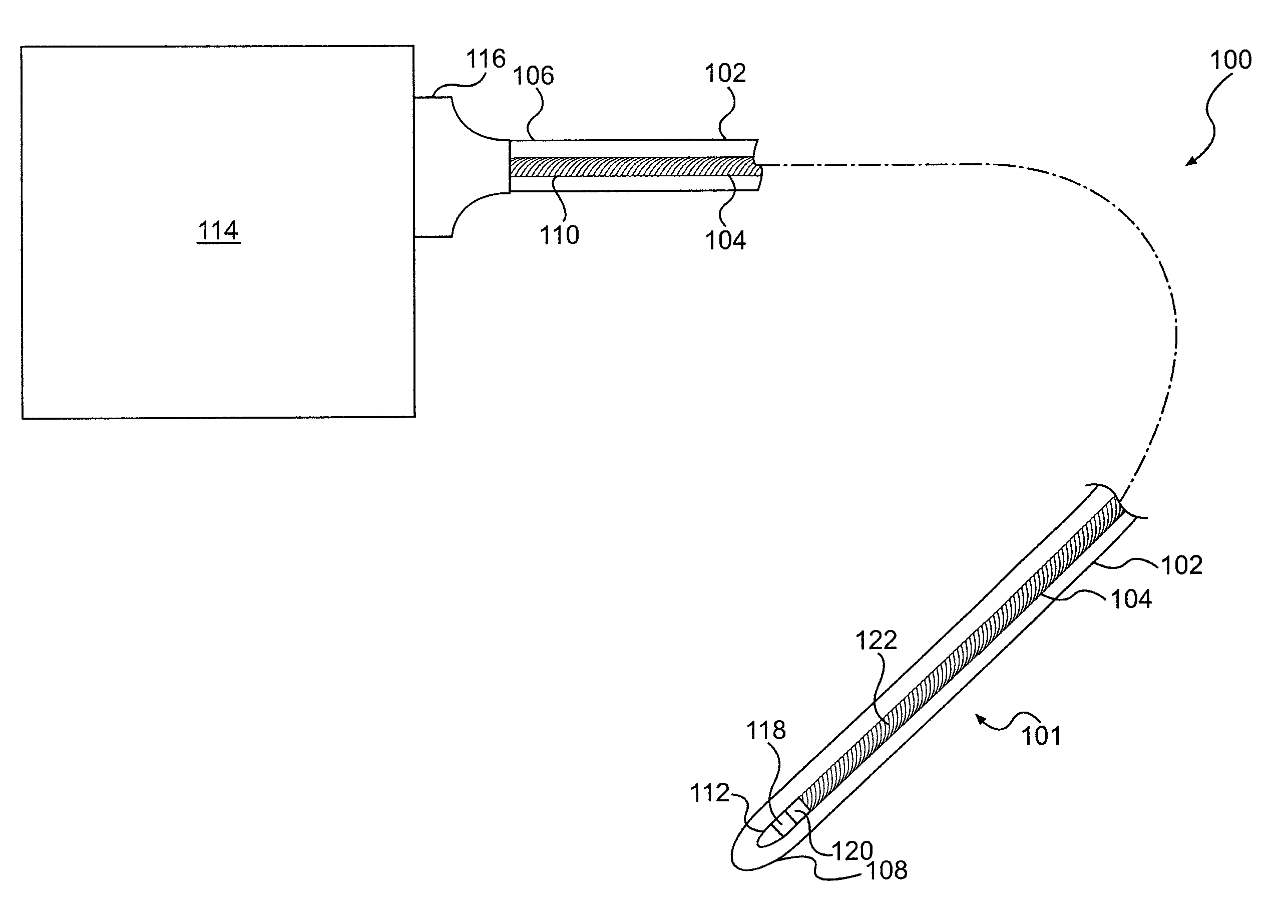
[0019]Referring specifically to FIG. 1, a rotational intravascular ultrasound probe 100 for insertion into a patient for diagnostic imaging is shown. The probe 100 comprises a catheter 101 having a catheter body 102 and a transducer shaft 104. The catheter body 102 is flexible and has both a proximal end portion 106 and a distal end portion 108. The catheter body 102 is a sheath surroun...


PUM


Abstract

An intravascular ultrasound probe is disclosed, incorporating features for utilizing an advanced transducer technology on a rotating transducer shaft. In particular, the probe accommodates the transmission of the multitude of signals across the boundary between the rotary and stationary components of the probe required to support an advanced transducer technology. These advanced transducer technologies offer the potential for increased bandwidth, improved beam profiles, better signal to noise ratio, reduced manufacturing costs, advanced tissue characterization algorithms, and other desirable features. Furthermore, the inclusion of electronic components on the spinning side of the probe can be highly advantageous in terms of preserving maximum signal to noise ratio and signal fidelity, along with other performance benefits.

Description

BACKGROUND[0001]Intravascular Ultrasound (IVUS) has become an important interventional diagnostic procedure for imaging atherosclerosis and other vessel diseases and defects. In the procedure, an IVUS catheter is threaded over a guidewire into a blood vessel of interest, and images are acquired of the atherosclerotic plaque and surrounding area using ultrasonic echoes. This information is much more descriptive than the traditional standard of angiography, which shows only a two-dimensional shadow of the vessel lumen. Some of the key applications of IVUS include: determining a correct diameter and length of a stent to choose for dilating an arterial stenosis, verifying that a post-stenting diameter and luminal cross-section area are adequate, verifying that a stent is well apposed against a vessel wall to minimize thrombosis and optimize drug delivery (in the case of a drug eluting stent) and identifying an exact location of side-branch vessels. In addition, new techniques such as vi...

Claims


Application Information

Patent Timeline
Patent Type & Authority Patents(United States)
IPC IPC(8): A61B8/14
CPCA61B8/12A61B8/445A61B8/4461A61B8/54G10K11/355A61B8/52A61B8/4483A61B8/4488A61B8/4472A61B8/56
Inventor CORL, PAUL DOUGLAS
Owner VOLCANO CORP
Learn More