
Methods for capacitance volume correction in fluid delivery systems

a fluid delivery system and capacitance volume technology, applied in the direction of suction devices, intravenous devices, other medical devices, etc., can solve the problems of phase lag, contaminating the contents of this syringe, and not addressing capacitance or compliance volume errors in a comprehensive manner, so as to reduce volume

Active Publication Date: 2013-03-26
BAYER HEALTHCARE LLC
View PDF15 Cites 38 Cited by
  • Summary
  • Abstract
  • Description
  • Claims
  • Application Information

AI Technical Summary

Benefits of technology

This approach enables precise delivery of a full required dosage of fluid as a sharp bolus, minimizing residual pressures and improving the accuracy of fluid delivery, thereby reducing waste and ensuring effective medical procedures.

Problems solved by technology

However, it is known from this patent that inertial forces of moving contrast material and expansion of the containers and tubing associated with the system and used to conduct the contrast material to the patient via the catheter can cause a phase lag between movement of the syringe plunger within the injector syringe and movement of contrast material out of the catheter and into the patient.
Unless precautions are taken with such common tubing merging arrangements, the contents of the driven syringe may be pushed into the un-driven syringe and contaminate the contents of this syringe.
However, these approaches do not address capacitance or compliance volume errors in a comprehensive manner and, as a result, fail to address the under-delivery or over-delivery of contrast to the patient resulting from compliance or capacitance volume in the system “fluid path” components.
As a result, less than optimal injection boluses may result and / or operation of the fluid delivery system can result in relatively large amounts of wasted contrast media.

Method used


Image

  • Methods for capacitance volume correction in fluid delivery systems
  • Methods for capacitance volume correction in fluid delivery systems
  • Methods for capacitance volume correction in fluid delivery systems

Examples


example

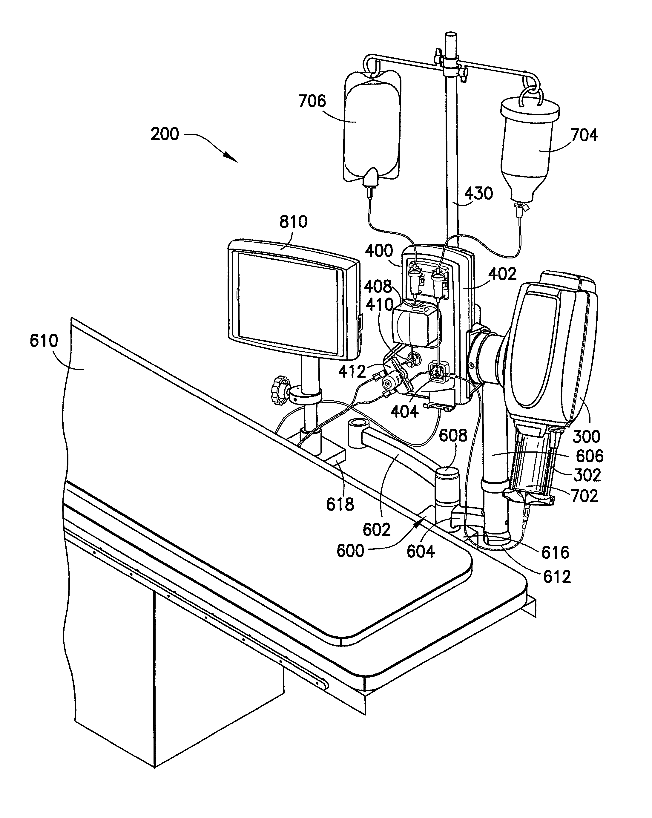
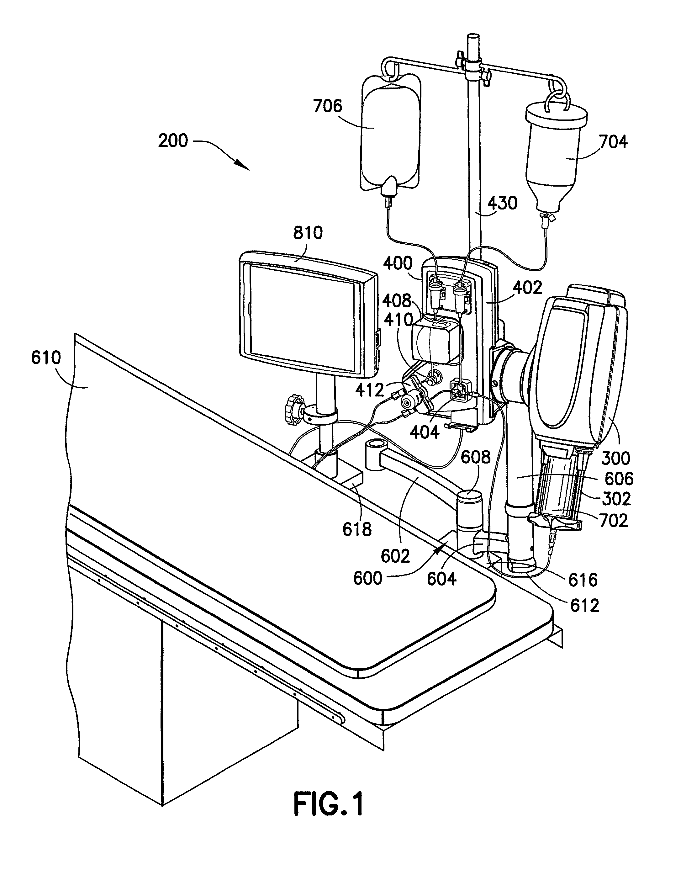
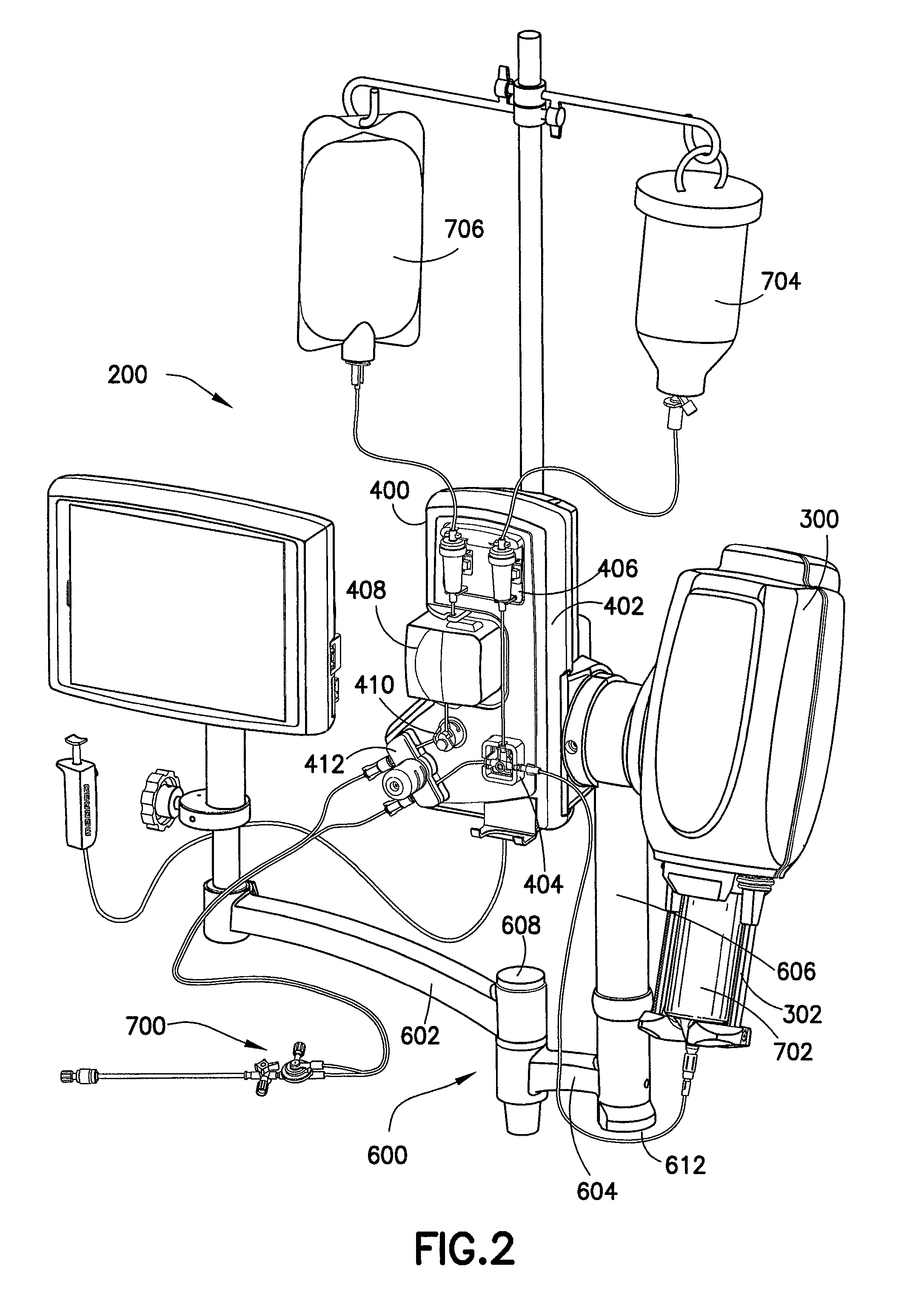
[0074]An empirical model of fluid delivery system 200 employing a syringe made of PET and analogous to syringe 702 was used to determine required over-travel of injector drive piston 306 needed to achieve volume accuracy of ±1.5%+1 ml. Static testing was first performed for pressures of 300, 600, and 900 psi and ending volumes of 125, 100, 75, 50, 30, and 10 ml. This testing entailed pressurizing syringe 702 while recording required displacement of syringe plunger 788 needed to achieve the aforementioned pressures. This relative displacement comprises the amount of capacitance volume believed to be indicative of truncated volume if multi-position valve 712 were closed at the end of movement of injector drive piston 306. The empirically derived relative displacement is then added as the value for over-travel to effectively deliver the required capacitance volume, also referred to previously as under-delivered fluid. Additionally, this value also comprises the value of retraction of i...


PUM


Abstract

Methods for capacitance volume correction in fluid-containing expandable bodies and associated fluid pathways are disclosed. The methods may be applied in fluid delivery systems used to supply fluids to patients during radiographic imaging procedures, including angiography. The methods control delivery of fluid to a downstream process, including providing a fluid-delivery expandable body and a pressurizing element in fluid communication with the downstream process, pressurizing the expandable body by moving the pressurizing element in the expandable body to reduce volume therein, determining an over-travel distance for the pressurizing element, and ceasing movement of the pressurizing element after allowing the pressurizing element to over-travel the over-travel distance to compensate for expansion of the expandable body under pressure. The expandable body may be a syringe and the pressurizing element may be a plunger disposed within the syringe. Movement of the pressurizing element may be controlled by an algorithm associated with a computer.

Description

CROSS REFERENCE TO RELATED APPLICATION[0001]This application is a 371 national phase application of PCT International Application No. PCT / US08 / 79160, filed on Oct. 8, 2008, and designating the United States of America, which claims the benefit of U.S. Provisional Application Ser. No. 60 / 981,128, filed on Oct. 19, 2007, the contents of which are incorporated herein by reference.BACKGROUND OF THE INVENTION[0002]1. Field of the Invention[0003]The embodiments of the invention disclosed herein relate generally to the field of diagnostic and therapeutic medical procedures involving the intravenous infusion of fluids such as contrast-enhanced radiographic imaging as an example and, further, to fluid delivery systems employing techniques to correct for capacitance volume effects in fluid-delivery bodies used in fluid delivery systems.[0004]2. Description of Related Art[0005]In many medical diagnostic and therapeutic procedures, a medical practitioner, such as a physician, injects a patient ...

Claims


Application Information

Patent Timeline
Patent Type & Authority Patents(United States)
IPC IPC(8): A61M31/00
CPCA61M5/14212A61M5/1452A61M5/14566A61M2005/14208A61M2205/3362
Inventor SPOHN, MICHAEL A.JOYCE, THOMAS P.
Owner BAYER HEALTHCARE LLC
Learn More