Mounted component inspection apparatus, component mounting machine comprising the mounted component inspection apparatus, and mounted component inspection method

a technology for component inspection and inspection apparatus, which is applied in the direction of metal-working machine components, instruments, manufacturing tools, etc., can solve the problems of not being able to perform correct recognition, not being able to ensure that the component library after this adjustment represents an improvement compared, and requiring time for re-adjusting the component library. to achieve the effect of improving the performance of the component library

Inactive Publication Date: 2013-03-26
PANASONIC CORP
View PDF2 Cites 6 Cited by
  • Summary
  • Abstract
  • Description
  • Claims
  • Application Information

AI Technical Summary

Benefits of technology

[0029]According to a desirable embodiment of the present invention, it is possible to confirm, quantitatively, whether the performance of a component library has been improved by adjustment, and it is possible to introduce a suitable component library rapidly. The present invention can also be applied to device inspections in the field of semiconductors, for example, as well as the inspection of mounted components in a production line for mounting components on a substrate.

Problems solved by technology

However, in this conventional mounted component inspection, if the recognition rate does not improve even when the templates are switched, then even supposing that the component library is adjusted to include template changes, it is not possible to ensure that the component library after this adjustment represents an improvement compared to the component library before adjustment.
Furthermore, false recognition means that correct recognition cannot be performed.
In this way, in the conventional mounted component inspection, since there is no means of confirming quantitatively that an improvement in the performance of the component library has been achieved by adjustment, then it has taken time until the level of this performance can be assessed, and therefore it has required time to re-adjust the component library.
Moreover, since it takes time until the satisfactory or unsatisfactory nature of the recognition rate is revealed, then unless similarities and differences between the component library before adjustment and the component library after adjustment are managed suitably, the time taken to re-adjust the library in order to return to the original component library progressively increases.
These problems are especially pronounced in cases where many different types of components are mounted, and where there is a plurality of component libraries requiring adjustment.
Furthermore, in this case, in the conventional mounted component inspection, since there is no means of confirming the improvement made in the performance of the component library through adjustment quantitatively, then it has been difficult to specify which component library should be adjusted.
Furthermore, if there are many different types of components to be mounted, then the management of recording of differences between the component libraries before adjustment and the component libraries after adjustment is complicated, and this places an increased load on the operator.
As described above, in the conventional mounted component inspection, it has not been possible to re-adjust the component libraries quickly.
Furthermore, in the mounted component inspection, the shape of the object under inspection is not uniform, but rather includes a plurality of shapes.
However, recently, specialist operators having sufficient expertise are not necessarily present in component mounting sites, and therefore it is necessary to improve the performance of the component libraries in consideration of this situation in the field.

Method used


Image

  • Mounted component inspection apparatus, component mounting machine comprising the mounted component inspection apparatus, and mounted component inspection method
  • Mounted component inspection apparatus, component mounting machine comprising the mounted component inspection apparatus, and mounted component inspection method
  • Mounted component inspection apparatus, component mounting machine comprising the mounted component inspection apparatus, and mounted component inspection method

Examples


first embodiment

[0046](First Embodiment)

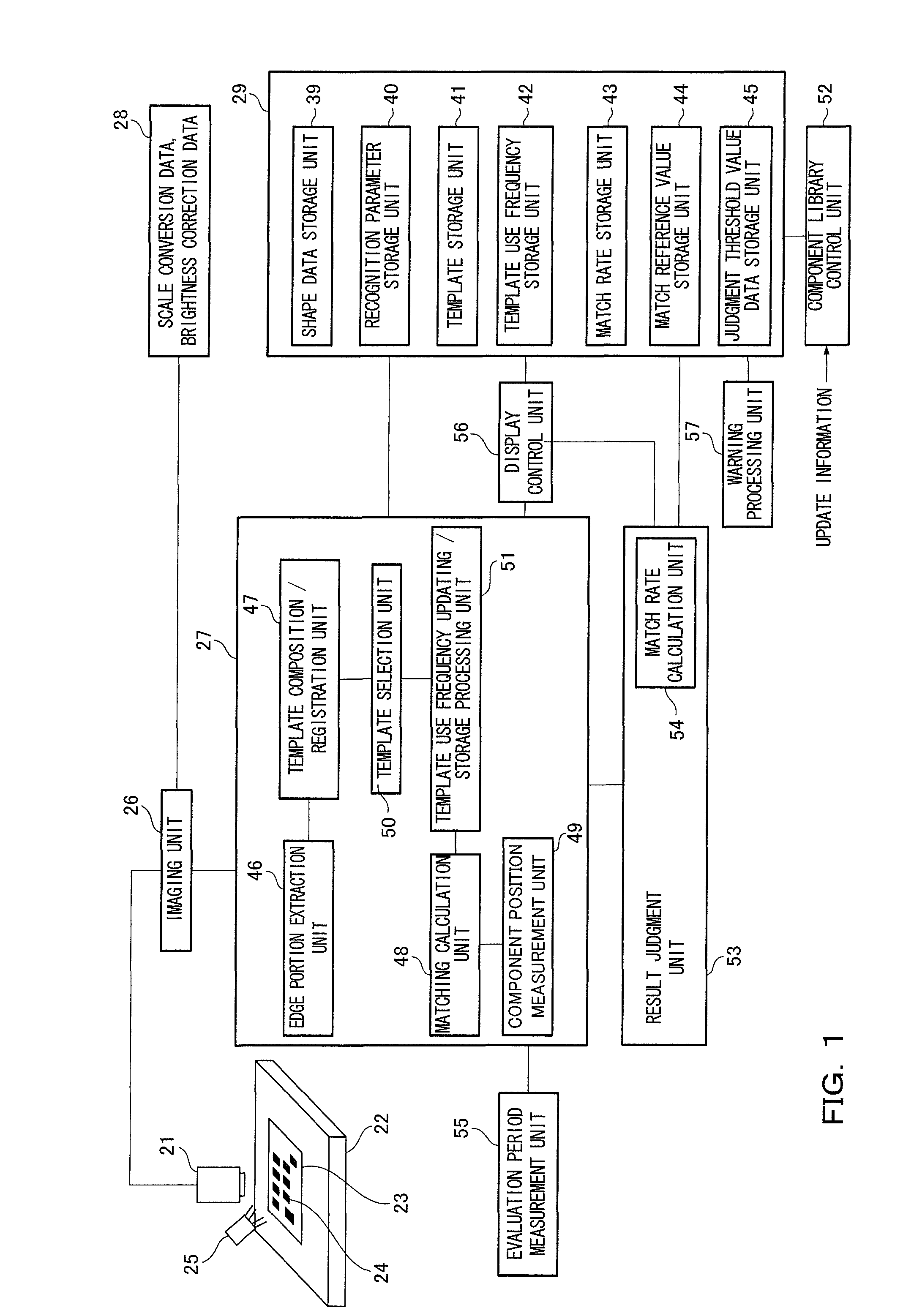
[0047]A first embodiment of the present invention is described in detail with reference to the drawings. FIG. 1 is a diagram showing the overview of the composition of a mounted component inspection apparatus according to the first embodiment of the present invention.

[0048]In FIG. 1, a camera 21 captures an image of a substrate 23 mounted on a stage 22. The substrate 23 is a circuit substrate, for example. A component 24 is mounted on the substrate 23. The component 24 is an electronic component, for example. Furthermore, illumination light is irradiated onto the substrate 23 from an illumination unit 25. The image captured by the camera 21 is input to an image processing unit 27 via an imaging unit 26. The imaging unit 26 converts the scale of the image captured by the camera 21 from meter units to pixel units, and corrects the brightness of the image, by using scale conversion data and brightness correction data stored in an equipment specific data storage ...

second embodiment

[0122](Second Embodiment)

[0123]Next, a second embodiment of the present invention is described in detail with reference to the drawings. Here, elements which are the same as those described in the first embodiment above are not explained, and only the points of difference from the first embodiment are described.

[0124]FIG. 9 is a diagram showing the overview of the composition of a mass production line for mounting components on a substrate according to the second embodiment of the present invention.

[0125]In FIG. 9, a printing machine 62 prints cream solder onto a substrate (not illustrated) which passes along the mass-production line. A high-speed mounter 63 mounts small chip components, mainly, on the substrate onto which the cream solder has been printed. A mounted component inspection machine 64 is one example of a mounted component inspection apparatus, and similarly to the first embodiment described above, the mounted component inspection machine 64 carries out the inspection o...

third embodiment

[0147](Third Embodiment)

[0148]Next, a third embodiment of the present invention is described in detail with reference to the drawings. Detailed descriptions of items which are the same as those described in the first and second embodiments are not given here.

[0149]FIG. 14 is a diagram showing a method of delivering a component library according to the third embodiment of the present invention.

[0150]In FIG. 14, a customer (recipient of a component library) signs a component library support contract with a manufacturer (supplier of the component library).

[0151]If the match rate of the component library used by the customer is lower than a warning threshold value, then the customer issues a notification to the manufacturer (step S21). More specifically, the customer gathers on a daily basis, in the form of daily reports, false recognition images where recognition has not been made accurately, of the images of components presenting a problem, and the customer reports these false recogni...


PUM

PropertyMeasurementUnit
polarityaaaaaaaaaa
compositionaaaaaaaaaa
brightnessaaaaaaaaaa

Abstract

A mounted component inspection apparatus according to the present invention includes: a component library holding inspection information; an inspection processing unit for inspecting a component under inspection using the component library; a match rate acquisition unit for acquiring a match rate indicating the degree to which the inspection information is suitable for the inspection by the inspection processing unit, on the basis of the result of the inspection by the inspection processing unit; and a judgment unit for selecting the inspection information having a higher match rate, of the inspection information before updating and the inspection information after updating. The component library can hold the inspection information before and after updating, and the inspection processing unit carries out the inspection using the inspection information before and after updating held in the component library.

Description

[0001]The disclosures of Japanese Patent Application No. 2009-017965 filed Jan. 29, 2009 and Japanese Patent Application No. 2010-012669 filed Jan. 25, 2010 including specification, drawings and claims are incorporated herein by reference in its entirety.BACKGROUND OF THE INVENTION[0002]1. Field of the Invention[0003]The present invention relates to the inspection of mounted components, for inspecting the presence or absence of a component at a prescribed position on a circuit substrate, a deviation from the ideal position of a component mounted on a circuit substrate, whether or not the direction of polarity of a component mounted on a circuit substrate is correct, and so on.[0004]2. Description of the Related Art[0005]Conventionally, the inspection of mounted components is carried out using a template recorded in a component library. Furthermore, one type of the mounted component inspection using a template is an inspection using a master template and a spare template, which is di...

Claims


Application Information

Patent Timeline
Patent Type & Authority Patents(United States)
IPC IPC(8): G06K9/00
CPCG01N21/956Y10T29/53174Y10T29/53013
Inventor UEDA, YOICHIRO
Owner PANASONIC CORP
Why Eureka
Try Eureka