Plasma display with a novel green-silicate phosphor

a green-silicate phosphor and display device technology, applied in the manufacture of electrode systems, electric discharge tubes/lamps, discharge tubes luminescnet screens, etc., can solve the problems of serious concern about display quality decline, and achieve excellent decay characteristics, short decay, and low decay characteristics

Inactive Publication Date: 2010-08-31
MAXELL HLDG LTD
View PDF5 Cites 5 Cited by
  • Summary
  • Abstract
  • Description
  • Claims
  • Application Information

AI Technical Summary

Benefits of technology

[0006]Recently, PDP devices having high performance are gaining recognition and are replacing monitors and television sets (TV) using cathode ray tubes, thereby, the use of large flat panel displays and thin TV sets has been rapidly expanding. As a result, there has been a demand for further improvements in performance. Concretely, there has been a demand to realize higher luminance for satisfying the display function for the television, higher emission efficiency for achieving higher luminance, to ensure a wide color reproduction range for replaying beautiful images, and to improve the video characteristics to allow viewers to comfortably appreciate video content such as movies.
[0007]For promoting higher performance of the PDP device, improvements in design and structure and improvements in the performance of the components specifically, the phosphor used in it, play important roles. Therefore, improvements in the emission efficiency and improvements in the response characteristics in the light emission are required of the phosphor.

Problems solved by technology

Therefore, when the use for televisions comes within sight and an improvement of the video characteristics is a strong requirement, there is a possibility that a problem such as decay which decreases the display quality becomes a serious concern.

Method used


Image

  • Plasma display with a novel green-silicate phosphor
  • Plasma display with a novel green-silicate phosphor
  • Plasma display with a novel green-silicate phosphor

Examples


first embodiment

[0164]To produce a PDP as a first embodiment of the present invention, first, an Eu2+-activated silicate green-emitting phosphor as an essential constituent member of the present invention was synthesized.

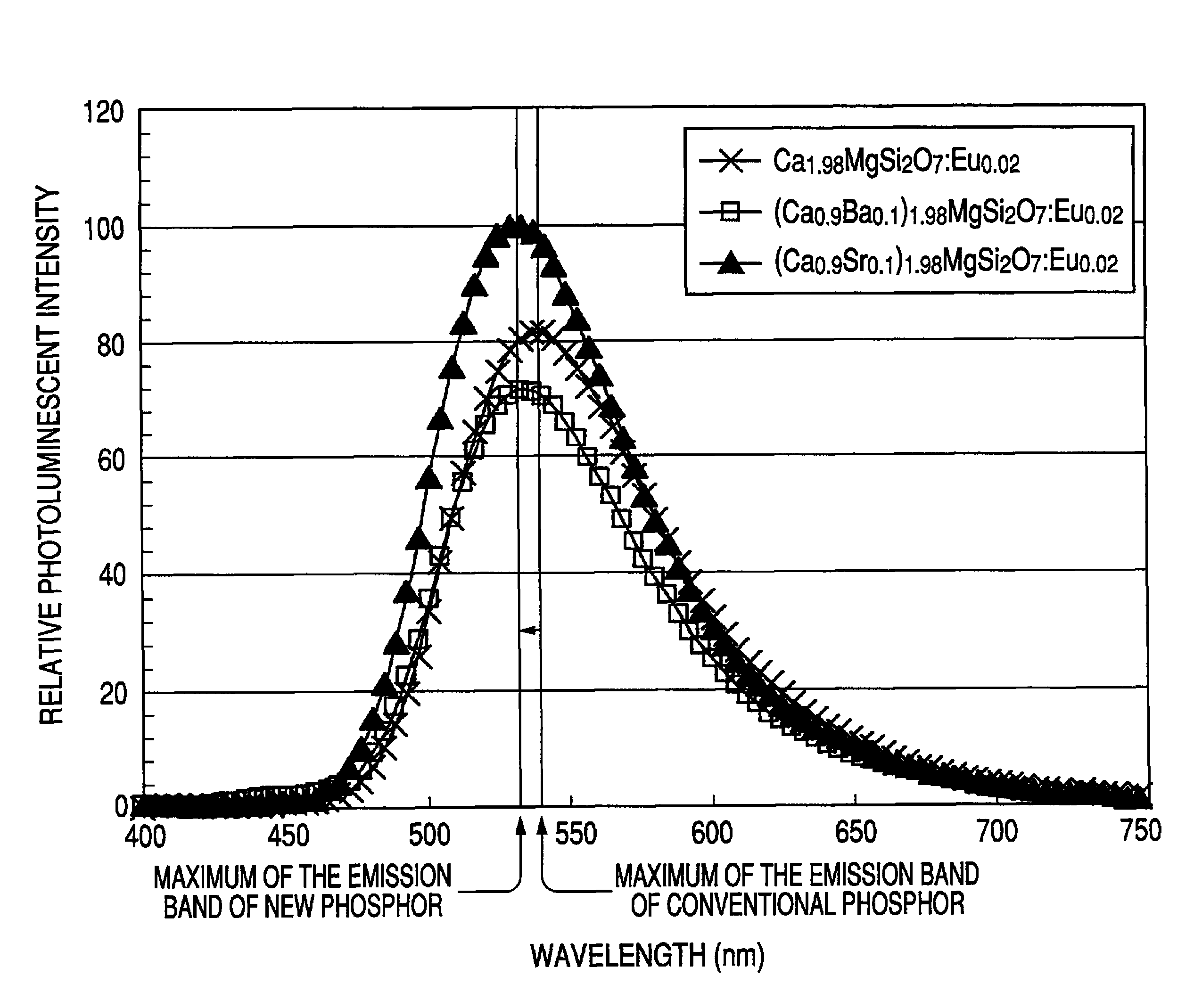
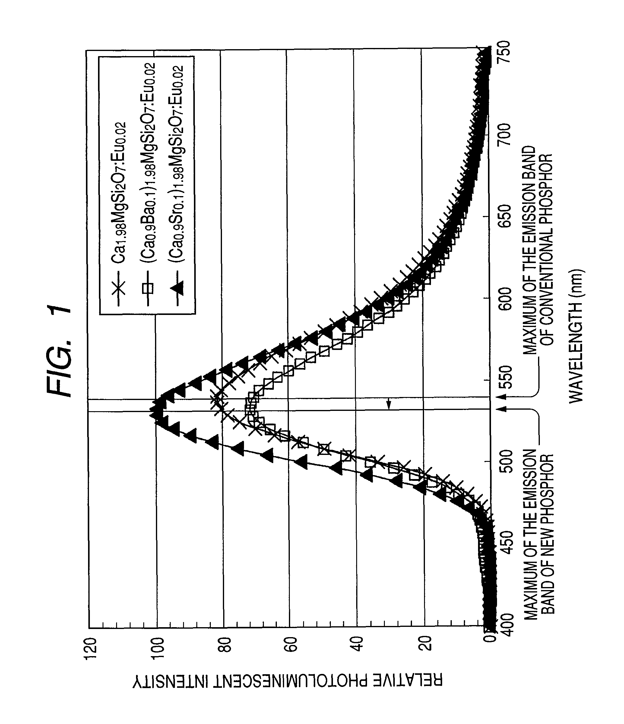
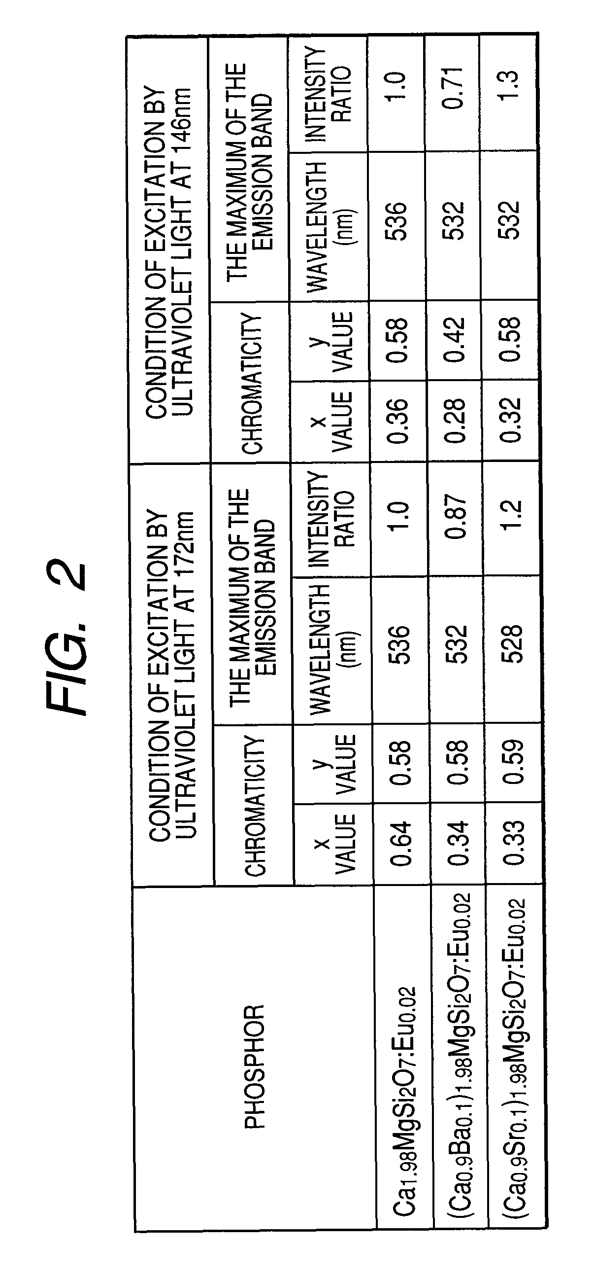
[0165]The composition of the first synthesized Eu2+-activated silicate green-emitting phosphor was (Ca0.9Sr0.1)1.98MgSi2O7:Eu0.02.

[0166]For the synthesis of a phosphor, first, 1.784 g (17.82 mmol) of CaCO3, 0.292 g (1.98 mmol) of SrCO3, 0.962 g (10.00 mmol) of MgCO3, 1.322 g (22.00 mmol) of SiO2, 0.0352 g (0.100 mmol) of Eu2O3, and 0.0160 g (0.300 mmol) of NH4Cl as a flux were respectively weighed and fully mixed in an agate mortar.

[0167]Thereafter, the obtained mixture was charged into a heat-resistant vessel and heated for 2 hours at 600° C. in atmosphere. Thereafter, it was further heated for 3 hours at 1200° C. in a reducing atmosphere. The obtained product was pulverized, washed with water and dried so as to obtain a silicate phosphor with the above composition.

[0168]Next, a E...

second embodiment

[0198]For another embodiment of the present invention, in order to produce a PDP using a green-emitting phosphor different from the first embodiment, first, a Eu2+-activated silicate phosphor as an essential constituent member of the present invention was synthesized.

[0199]The composition of the first synthesized Eu2+-activated silicate green-emitting phosphor was (Ca0.9Sr0.1)1.97MgSi2O7:Eu0.03.

[0200]For the synthesis of a phosphor, first, 0.887 g (8.86 mmol) of CaCO3, 0.146 g (0.99 mmol) of SrCO3, 0.481 g (5.00 mmol) of MgCO3, 0.601 g (10.00 mmol) of SiO2, 0.0264 g (0.075 mmol) of Eu2O3, and 0.196 g (2.00 mmol) of NH4Br as a flux are respectively weighed and fully mixed in an agate mortar.

[0201]Thereafter, the obtained mixture was charged into a heat-resistant vessel and heated for 2 hours at 600° C. in atmosphere. Thereafter, it was further heated for 3 hours at 1200° C. in a reducing atmosphere. The obtained product was pulverized, washed with water and dried so as to obtain a si...

third embodiment

[0231]A PDP was prepared by using the Eu2+-activated silicate phosphor (Ca0.7Sr0.3)1.97MgSi2O7:Eu0.03 explained in the second embodiment as a green-emitting phosphor constituting a green color phosphor layer.

[0232]The configuration and the method of preparation thereof were the same as the PDO 100 shown in the first embodiment, but particles of the phosphor (Ca0.7Sr0.3)1.97MgSi2O7:Eu0.03 explained in the second embodiment were used for the phosphor particles included in the green phosphor layer 10. Therefore, since details of the other configuration and the method of preparation of the PDP and the PDP device with regard to the third embodiment are omitted, only the main parts will be briefly explained referring to the corresponding parts of FIG. 4 to FIG. 7. Note that the corresponding same components in the PDP configuration are denoted by the same reference symbols throughout the drawings for describing the embodiment, and a repetitive description hereof will be omitted.

[0233]A PD...


PUM

PropertyMeasurementUnit
mole fractionaaaaaaaaaa

Abstract

Using Eu2+ as the luminescence center for a green-emitting phosphor, a plasma display panel and a PDP device using it are configured by using an Eu2+-activated silicate green-emitting phosphate (Ca1-xM1x)2-e.M2.Si2O7:Eue with improved decay characteristics. In the formula, M1 is at least one element selected from the group containing Sr and Ba; M2 is at least one element selected from the group containing Mg and Zn; and x indicates the mole fraction of the component M1 and e indicates the mole fraction of Eu respectively satisfy the following conditions: 0<x<1 and 0.001≦e≦0.2.

Description

CLAIM OF PRIORITY[0001]The present application claims priority from Japanese patent application JP 2007-226642 filed on Aug. 31, 2007, the content of which is hereby incorporated by reference into this application.FIELD OF THE INVENTION[0002]The present invention relates to a plasma display device, in particular, it relates to a plasma display device such as a plasma display panel using a phosphor, specifically, a Eu (europium) activated silicate green-emitting phosphor which emits the light by being exciting by ultraviolet light in the vacuum ultraviolet region as a light emitting device.BACKGROUND OF THE INVENTION[0003]In recent years, there has been an increasing demand to reduce the thickness of display devices represented by television sets and monitors for personal computers for saving installation space. As a display device capable of being made thin, the development of liquid crystal displays (LCD) has been aggressively pursued in which a display device is composed of a plas...

Claims


Application Information

Patent Timeline
Patent Type & Authority Patents(United States)
IPC IPC(8): H01J11/02H01L33/00C09K11/08C09K11/59C09K11/64C09K11/78C09K11/79C09K11/80C09K11/81C09K11/83H01J9/227H01J11/12H01J11/22H01J11/24H01J11/26H01J11/34H01J11/36H01J11/38H01J11/40H01J11/42H01J11/50
CPCC09K11/7734H01J1/63H01J11/12H01J2211/50C09K11/77342H01J11/42H01J11/50
Inventor OAKU, HITOSHISAKUMA, HIROTAKAOKAZAKI, CHOICHIRO
Owner MAXELL HLDG LTD
Why Eureka
Try Eureka