Floor covering

a technology for floor coverings and cables, applied in the direction of cables for vehicles/pulleys, structural elements, building components, etc., can solve the problem of unsatisfactory height offset on the sid

Active Publication Date: 2013-04-02
SCHULTE GUIDO
View PDF11 Cites 26 Cited by
  • Summary
  • Abstract
  • Description
  • Claims
  • Application Information

AI Technical Summary

Benefits of technology

[0013]The run-up face is a contour in form of a recess in the groove. The recess itself is arranged in the groove bottom. In particular, the recess can be produced with a saw cut, so that the recess has the contour of a segment of a circle. The segment of the circle can also be rounded in its transition regions to the groove bottom, thereby producing a recess with a sinusoidal shape. This is a result of the production process, because the individual panel elements move during processing parallel to the saw blade which is used to introduce the recess. Unless this movement occurs completely synchronously, the edge region is smoothed, thus producing rounded transitions. Important is the function of the run-up face, namely that it functions as a contoured abutment to effect a lateral displacement of the head spring during its longitudinal displacement.

Problems solved by technology

While insertion of the head springs in the factory with a machine does not pose a problem, it must be ensured when installing the floor covering that the head springs are, on one hand, easily displaceable and, on the other hand, do not allow movement of the abutting head sides in the vertical direction, which would lead to an undesirable height offset on the side that is visible, in particular when a load is applied to the panel elements near the head sides.

Method used


Image

  • Floor covering
  • Floor covering
  • Floor covering

Examples


Embodiment Construction

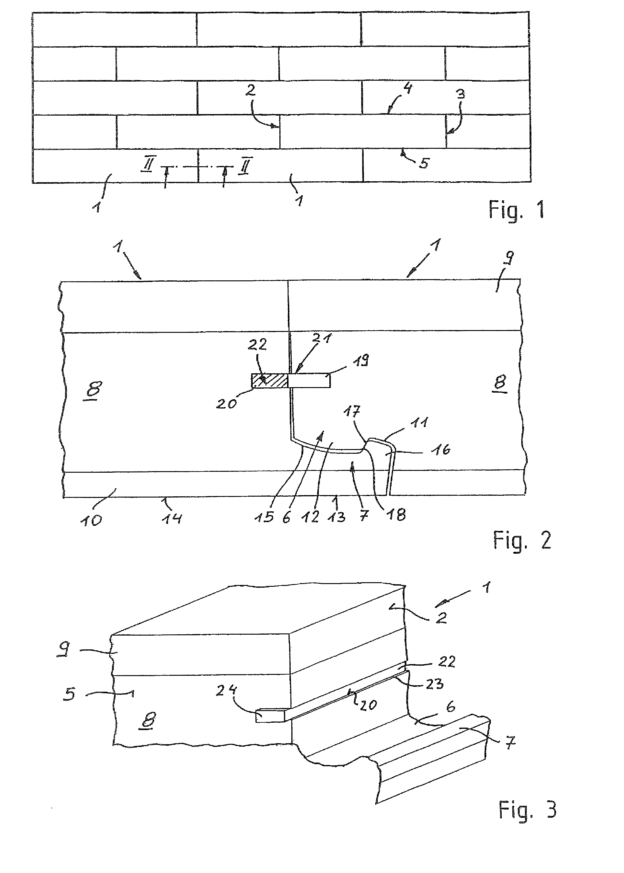
[0022]FIG. 1 shows a floor covering made of the plurality of interlocked rectangular panel elements 1. The panel elements 1 have locking rails on their respective head sides 2, 3 and on their respective longitudinal sides 4, 5. The locking rails of adjacent panels in the covering engage with each other in the installation position.

[0023]Locking rails 6, 7 on the head sides 2 and 3, respectively, of a panel element 1 are illustrated in FIG. 2. FIG. 2 shows a vertical cross-section through the head-side joint region between two panel elements 1, when viewing the connection at the head sides 2, 3. The unillustrated locking rails on the longitudinal sides of a panel element 1 may be configured different from the locking rails 6, 7.

[0024]A panel element 1 is made of a support layer 8 made of fiber material, typically a highly or moderately compacted fiber plate, wherein the support layer 8 has a top-side cover layer 9 and a bottom-side back pull 10. The cover layer may be made from a dec...


PUM


Abstract

Disclosed is a floor covering consisting of a plurality of panel elements (1) that can be laid in combination with each other. On the front sides (2, 3) and longitudinal sides (4, 5), the panel elements (1) have locking strips (6, 7) that engage with each other in the assembled position in a covering in which panel elements (1) adjoin each other. The front sides (2, 3) of the panel elements (1) have grooves (19, 20). The grooves (19, 20) of two abutting front sides (2, 3) are aligned and form a locking channel (21) for accommodating a front spring (22) that is pre-assembled in one of the grooves (20). The front spring (22) projects from an end of the groove (20) that faces the longitudinal side (5) of the panel element (1) and can be moved in part from one groove (20) into the corresponding groove (19) of the adjoining panel element (1) by sliding the projecting end (24) of the front spring (22) into the groove (20). The groove (20) that accommodates the front spring (22) has at least one recess (45) within which a stop surface (25) is formed and into which a cam (43) of the front spring (22) engages. The front spring (22) has a wavy shape. The wavy sides of the front spring (22) face a decorative side and a bottom side of the panel elements (1). The orientation of the troughs (27) and crests (26) of the wavy zones (28, 29) should correspond to the direction of travel (V) of the front spring (22) when the front spring (22) is slid into the recess (45) and the cam (43) rests thereagainst.

Description

CROSS-REFERENCES TO RELATED APPLICATIONS[0001]This application is the U.S. National Stage of International Application No. PCT / DE2009 / 001208, filed Aug. 27, 2009, which designated the United States and has been published as International Publication No. WO 2010 / 028621 and which claims the priority of German Patent Application, Serial No. 10 2008 047 099.6, filed Sept. 12, 2008, pursuant to 35 U.S.C. 119(a)-(d).BACKGROUND OF THE INVENTION[0002]The invention relates to a floor covering composed of interlocked panel elements.[0003]According to WO 2008 / 017301 A2, floor coverings made of a plurality of interconnected panel elements, which have interlocking rails at their head sides and the longitudinal sides engaging in the installed position with adjacent panel elements of a floor covering are known in the art. Grooves are provided in the head sides, wherein the grooves of two abutting head sides correspond with each other and form a locking channel for receiving a head spring. The head...

Claims


Application Information

Patent Timeline
Patent Type & Authority Patents(United States)
IPC IPC(8): E04B2/00
CPCE04F15/02E04F15/04E04F2201/0153E04F2201/0169Y10T403/589E04F2201/0541E04F2201/0547Y10T403/76E04F2201/0523F16B2200/73
Inventor SCHULTE, GUIDO
Owner SCHULTE GUIDO
Why Eureka
Try Eureka