ASU nitrogen sweep gas in hydrogen separation membrane for production of HRSG duct burner fuel
a technology of duct burner fuel and hydrogen separation membrane, which is applied in the direction of separation processes, machines/engines, energy input, etc., can solve the problems of high cosub>2 /sub>sequestration cost and insufficient heat in the gas turbine exhaust to superheat the steam generated in the igcc process, so as to reduce nox production, reduce h2 permeation partial pressure, and increase flux
- Summary
- Abstract
- Description
- Claims
- Application Information
AI Technical Summary
Benefits of technology
Problems solved by technology
Method used
Image
Examples
example 1
Power-Only IGCC Plant with CO2 Capture
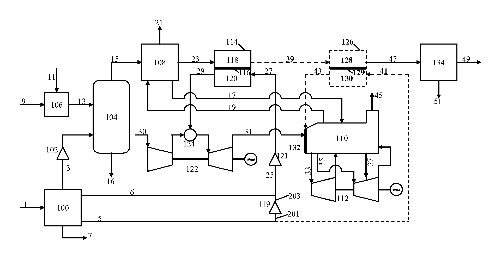
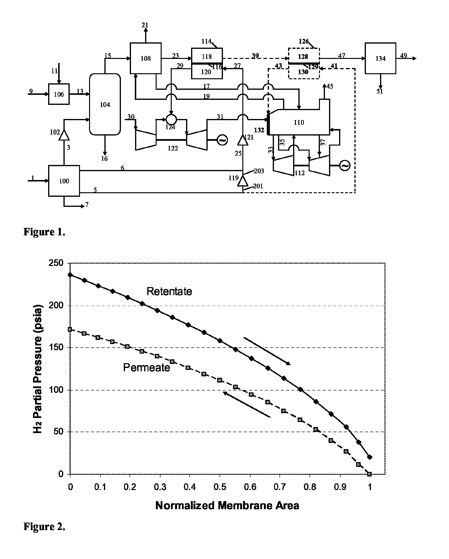
[0022]FIG. 1 shows a simplified process flow diagram (PFD) for an embodiment of the present invention in which a power-only (i.e. without high-purity H2 production) IGCC plant with CO2 capture utilizes HTM technology to make a H2—N2 fuel mixture for combustion in the gas turbine and the HRSG duct burner. The portions of the plant representing aspects of the present invention are drawn with dashed lines and / or labeled with bold font in the diagram. While not to be construed as limiting, an exemplary stream summary is given in Table 1 for the computer-simulated example case described below.
[0023]
TABLE 1Stream summary for PFD shown in FIG. 1.Stream9315233947492943Flow (lbmol / hr)58092616038680212702053012700376801592Flow (kpph)268.1187.1526.5713.6678.6677.1546.3607.125.6Temp (F.)1971750750750100750750Pressure (psia)615500490485220037520H2 (%)32.047.34.10.61.045.645.6CO (%)39.91.32.42.50.50.00.0CO2 (%)11.029.954.456.395.30.00.0H2O (%)13.720.236.738.0...
example 2
Co-Production of H2 and Electrical Power in an IGCC Plant with CO2 Capture
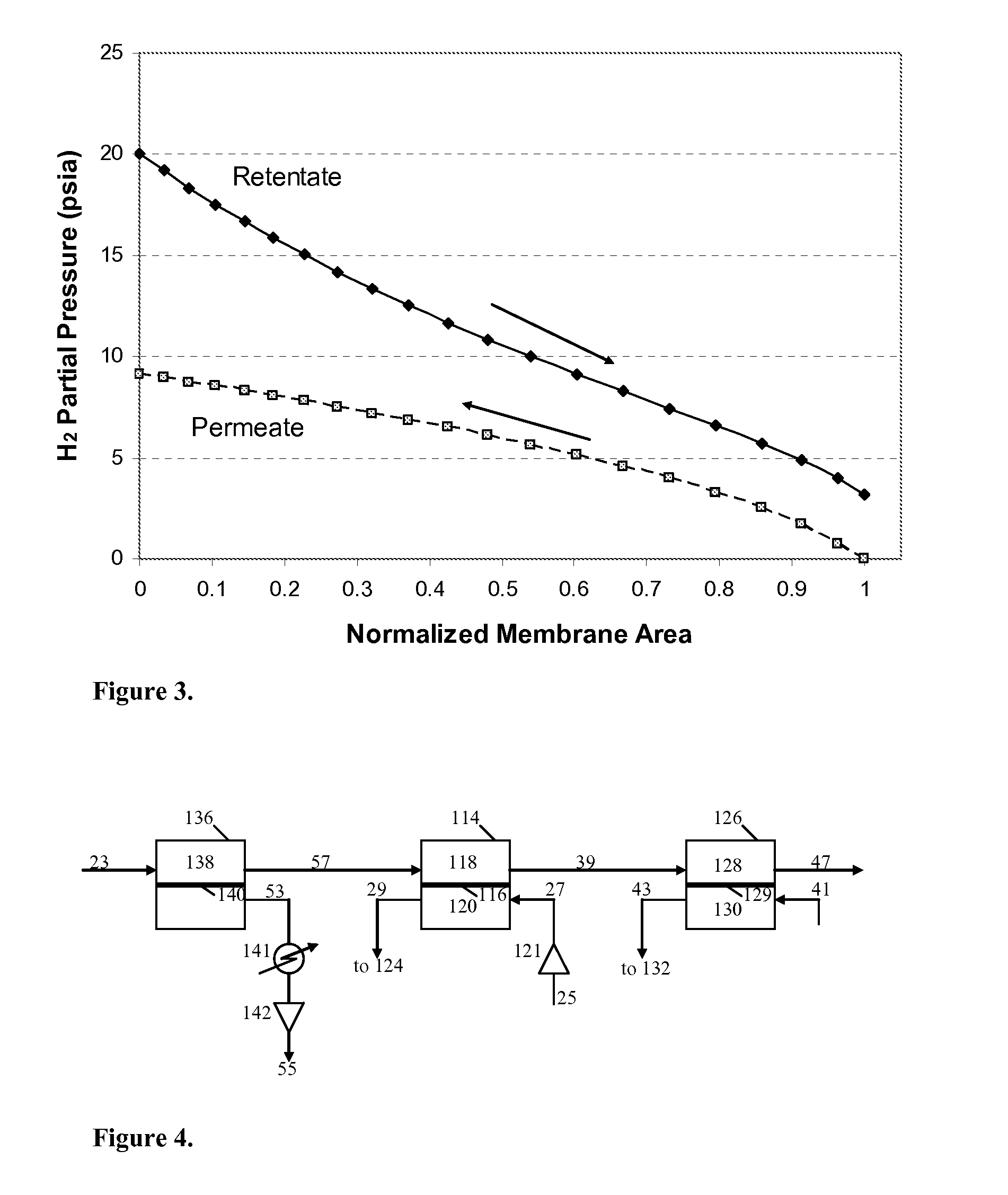
[0035]An exemplary arrangement of HTMs for co-production of H2 (e.g., high-purity H2) and electrical power in an IGCC plant with CO2 capture in accordance with an alternative embodiment of the present invention is illustrated in FIG. 4. As used in the present invention, “high-purity H2” gas, it is meant H2 gas that is at least 95% by volume H2. More preferably, such gas will be at least 99% by volume H2 and most preferably, such gas will be greater than 99.9% by volume H2. The process flow diagram (PFD) only shows the portions for the HTMs of the IGCC plant. The processing and equipment upstream and downstream of the HTMs can be the same as described above and shown in FIG. 1. The stream summary for this particular computer-simulated example is given in Table 2.
[0036]
TABLE 2Stream summary for PFD shown in FIG. 4.Stream23573947532943Flow (lbmol / hr)386803029023030205208389157105438Flow (kpph)713.6696.7682.1677.0...
PUM
 Abstract
Description
Claims
Application Information
 - R&D
- Intellectual Property
- Life Sciences
- Materials
- Tech Scout
- Unparalleled Data Quality
- Higher Quality Content
- 60% Fewer Hallucinations
Browse by: Latest US Patents, China's latest patents, Technical Efficacy Thesaurus, Application Domain, Technology Topic, Popular Technical Reports.
© 2025 PatSnap. All rights reserved.Legal|Privacy policy|Modern Slavery Act Transparency Statement|Sitemap|About US| Contact US: help@patsnap.com


