
Method and device for gas supply during cardiopulmonary resuscitation

a cardiopulmonary resuscitation and gas supply technology, applied in the direction of tracheal tubes, artificial respiration, medical atomisers, etc., can solve the problems of irreparable damage to the brain and other organs, permanent damage to the heart, etc., to alleviate, eliminate or mitigate one or more of the above-identified deficiencies and disadvantages.

Inactive Publication Date: 2013-04-02
IGELOSA LIFE SCI
View PDF19 Cites 8 Cited by
  • Summary
  • Abstract
  • Description
  • Claims
  • Application Information

AI Technical Summary

Benefits of technology

[0012]Accordingly, an object of the present invention is to mitigate, alleviate or eliminate one or more of the above-identified deficiencies and disadvantages singly or in any combination.

Problems solved by technology

If there is no blood flow for more than about 15 minutes, the brain and other organs will normally develop irreparable damage.
One of the problems of CPR that needs attention is to obtain a sufficient pressure differential between the aorta and the right atrium, so that a sufficient coronary perfusion pressure is obtained, otherwise the heart will suffer permanent damage.
Another problem is to obtain a low pressure in the pulmonary veins wherein blood is transported from the body and into the thorax, so that a sufficient refill of the thorax is obtained.

Method used


Image

  • Method and device for gas supply during cardiopulmonary resuscitation
  • Method and device for gas supply during cardiopulmonary resuscitation
  • Method and device for gas supply during cardiopulmonary resuscitation

Examples


Embodiment Construction

[0039]Below, several embodiments of the invention will be described with references to the drawings. These embodiments are described in illustrating purpose in order to enable a skilled person to carry out the invention and to disclose the best mode. However, such embodiments do not limit the invention. Moreover, other combinations of the different features are possible within the scope of the invention.

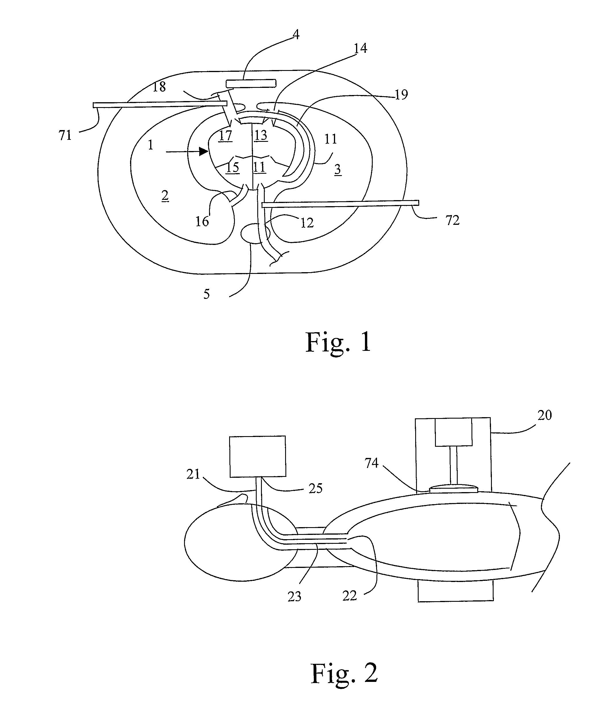
[0040]FIG. 1 is a cross-sectional view of the thorax of a patient, comprising a heart 1 in a horizontal section and two lungs 2, 3 in a vertical section. The heart 1 is positioned between a sternum 4 and a spine 5, which are shown schematically.

[0041]The heart 1 comprises a right atrium 11 connected to the vena cava 12 and a right ventricle 13 connected to the lung arteries 14. The blood is returned from the lungs to the left atrium 15 via the lung veins 16 and is pumped out to the aorta 18 by means of the left ventricle 17. The coronary arteries 19 supply blood to the heart and exte...


PUM


Abstract

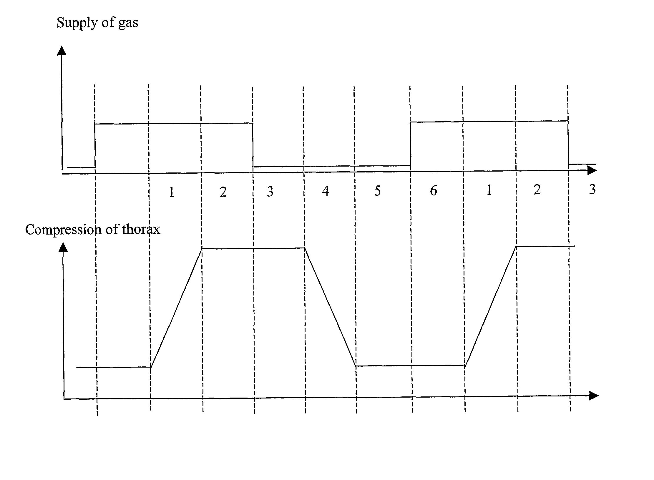
A method and device for providing ventilation gas to a patient during cardiopulmonary resuscitation. The device comprises: a gas source for supplying oxygen to the bronchi of the patient and a switch valve for initiating and terminating the gas supply. The switch valve is operated synchronous with the cardiopulmonary resuscitation cycle so that the switch valve operates with the same cycle as the cardiopulmonary resuscitation cycle but off-set in relation to the cardiopulmonary resuscitation cycle. The gas supply is initiated between 25% and 2% of the cycle time before the start of a compression stroke and is terminated between 2% and 30% of the cycle time after the start of a compression stroke. Alternatively, the gas supply is initiated between 25% and 48% of the cycle time after the termination of a compression stroke and is and terminated between 52% and 80% after the termination of a compression stroke.

Description

[0001]This application claims the benefit of U.S. provisional application Ser. No. 61 / 198,745 filed Nov. 10, 2008.AREA OF THE INVENTION[0002]The present invention relates to a method and system for supplying ventilation gas to the lungs of a patient during cardiopulmonary resuscitation, CPR, more specifically mechanical cardiopulmonary resuscitation, mCPR.BACKGROUND OF THE INVENTION[0003]When a patient suffers cardiac arrest, it is required to initiate life-saving techniques as soon as possible, preferably within 8 minutes. If there is no blood flow for more than about 15 minutes, the brain and other organs will normally develop irreparable damage.[0004]A previously known type of CPR is to manually compress the breastbone of the patient and to mechanically inflate the lungs of the patient.[0005]A mechanical device for performing mCPR is known in Sweden under the trademark LUCAS® and is described in the documents SE 521141 and WO 2005 / 046558. Generally, the device comprises a piston ...

Claims


Application Information

Patent Timeline
Patent Type & Authority Patents(United States)
IPC IPC(8): A61M16/20
CPCA61M16/04A61M16/10A61M16/0051A61M16/205A61M16/0484A61M16/204A61M11/00A61H31/007A61M2016/0027A61M2016/0042A61M2202/0208A61M2205/50A61M2230/202A61M2230/205A61M2230/30A61M2230/432A61M2230/005A61M2016/0413A61M16/042A61M16/0486A61M16/024A61H31/00
Inventor STEEN, STIGPASKEVICIUS, AUDRIUS
Owner IGELOSA LIFE SCI
Learn More