Thermal-acoustic sections for an aircraft

a technology of thermo-acoustic sections and aircraft, which is applied in the direction of generators/motors, instruments, transportation and packaging, etc., can solve the problems of significant increase in the noise transmitted through the fuselage to the aircraft cabin, and achieve the effects of reducing noise, promoting noise absorption, and reducing nois

Active Publication Date: 2013-04-09
GULFSTREAM AEROSPACE CORP
View PDF14 Cites 17 Cited by
  • Summary
  • Abstract
  • Description
  • Claims
  • Application Information

AI Technical Summary

Benefits of technology

[0006]In accordance with another exemplary embodiment, a thermal-acoustic section for an aircraft for reducing noise along an acoustic path produced from an acoustic source is provided. The thermal-acoustic section comprises a plurality of juxtaposed porous layers forming a thermal-acoustic stack. The thermal-acoustic stack has a first outermost portion, a second outermost portion, and a central portion that is disposed between the first and second outermost portions. The thermal-acoustic stack is configured to be positioned along the acoustic path such that the noise from the acoustic source is incident to the first outermost portion. The first outermost portion has a first relatively high characteristic acoustic impedance that is effective to reflect a substantial portion of the noise away from the thermal-acoustic stack and to allow a transmitted portion of the noise to enter the thermal-acoustic stack. The thermal-acoustic stack has a gradually decreasing characteristic acoustic impedance from the first outermost portion to the central portion and a gradually increasing characteristic acoustic impedance from the central portion to the second outermost portion to improve the transmission loss of the thermal-acoustic stack.

Problems solved by technology

The lower mass and higher stiffness structures are structurally very efficient, but unfortunately result in a significant increase in the noise transmitted through the fuselage to the aircraft cabin.

Method used


Image

  • Thermal-acoustic sections for an aircraft
  • Thermal-acoustic sections for an aircraft
  • Thermal-acoustic sections for an aircraft

Examples


Embodiment Construction

[0015]The following Detailed Description is merely exemplary in nature and is not intended to limit the invention or the application and uses of the invention. Furthermore, there is no intention to be bound by any theory presented in the preceding background or the following detailed description.

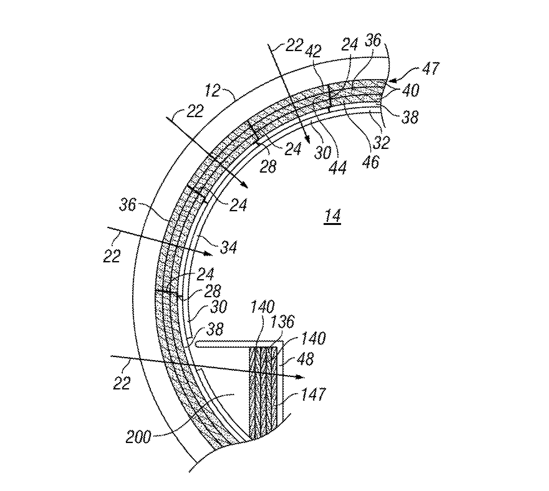
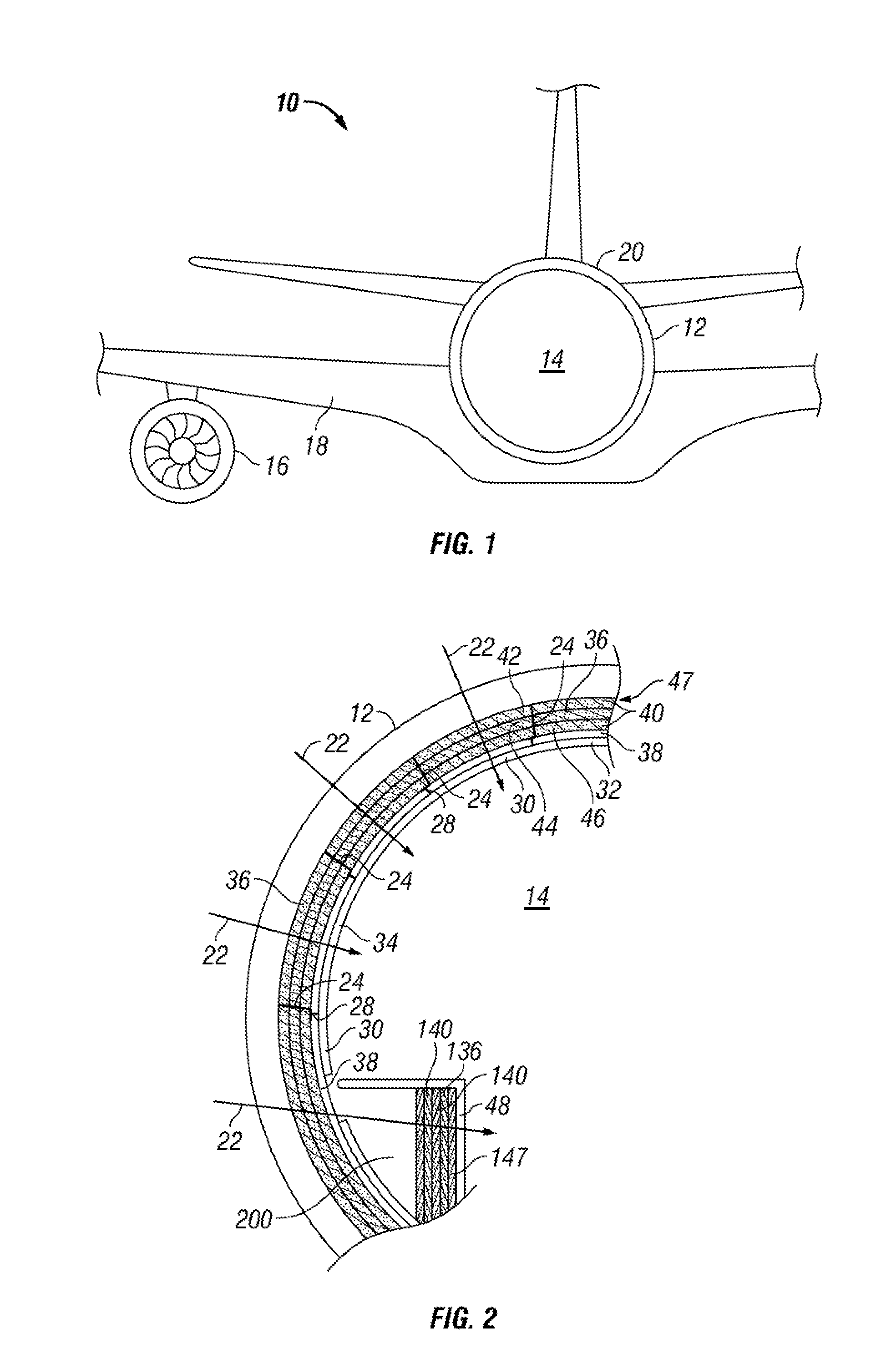
[0016]Various embodiments contemplated herein relate to thermal-acoustic sections for an aircraft for reducing noise. The exemplary embodiments taught herein provide a thermal-acoustic section comprising a plurality of juxtaposed porous layers stacked together preferably in direct contact with each other to form a thermal-acoustic stack. The thermal-acoustic stack is positioned along an acoustic path, such as, for example, between an aircraft fuselage and an interior cabin panel to reduce the noise passing through the fuselage to the aircraft cabin. Alternatively, the thermal-acoustic stack can be arranged elsewhere in the aircraft to reduce undesirable noise e.g., absorb undesirable noise.

[...


PUM

PropertyMeasurementUnit
acoustic impedanceaaaaaaaaaa

Abstract

Embodiments of thermal-acoustic sections for an aircraft for reducing noise along an acoustic path produced from an acoustic source are provided herein. The thermal-acoustic section comprises a first porous layer having a first characteristic acoustic impedance. A second porous layer is disposed adjacent to the first porous layer and has a second characteristic acoustic impedance that is greater than the first characteristic acoustic impedance. The thermal-acoustic section is configured to be positioned along the acoustic path such that at least a portion of the noise from the acoustic source is directed through the first porous layer to the second porous layer to promote absorption of the noise.

Description

TECHNICAL FIELD[0001]The present invention relates generally to noise reduction for an aircraft, and more particularly relates to thermal-acoustic sections that include multiple porous layers arranged together for reducing noise for the aircraft.BACKGROUND[0002]An Aircraft typically has various sections of their structure and / or interior cabin trim that incorporate thermal-acoustic packages for thermal insulation and reducing the noise that is transmitted into the cabin from outside of the fuselage, such as by the engines, the turbulent boundary layer over the fuselage, and the like, and that is directed inward to the aircraft cabin. For example, an aircraft with a metallic fuselage commonly has a layer of thermal-acoustic fibrous material interposingly positioned in the frame of the fuselage. The fibrous material helps to thermally insulate and reduce the noise passing through the fuselage to the aircraft cabin, providing a quieter, more comfortable and desirable environment for th...

Claims


Application Information

Patent Timeline
Patent Type & Authority Patents(United States)
IPC IPC(8): E04B1/82E04B1/84H02N2/00B32B3/12B32B7/02
CPCB64C1/40B32B5/32B32B7/02B29C66/11B29C66/1122B64C1/00G10K11/00B29C66/43E04B1/82E04B1/84B29C66/1142B32B3/12B29C65/00G10K11/02B32B5/26Y10T428/24149B32B2250/02B32B2250/03B32B2250/04B32B2250/05B32B2250/20B32B2250/22B32B2266/0257B32B2266/0285B32B2266/06B32B2307/102B32B2307/718B32B2605/18B29K2105/04Y02T50/40
Inventor WANG, TONGANMAXON, JR., JOHN WILLETTFOOSE, ANDREWHORNICK, DAVID CHARLESFILA, JOSEF
Owner GULFSTREAM AEROSPACE CORP
Why Eureka
Try Eureka