3-point wheelchair passenger securement system
a securement system and wheelchair technology, applied in the field of wheelchair passenger securement methods, vehicles, systems, etc., can solve the problems of increasing installation costs, increasing the cost of components and labor, and reducing the safety of wheelchair passengers, so as to eliminate a potential tripping hazard and eliminate an obstacle for wheelchair passengers
- Summary
- Abstract
- Description
- Claims
- Application Information
AI Technical Summary
Benefits of technology
Problems solved by technology
Method used
Image
Examples
first embodiment
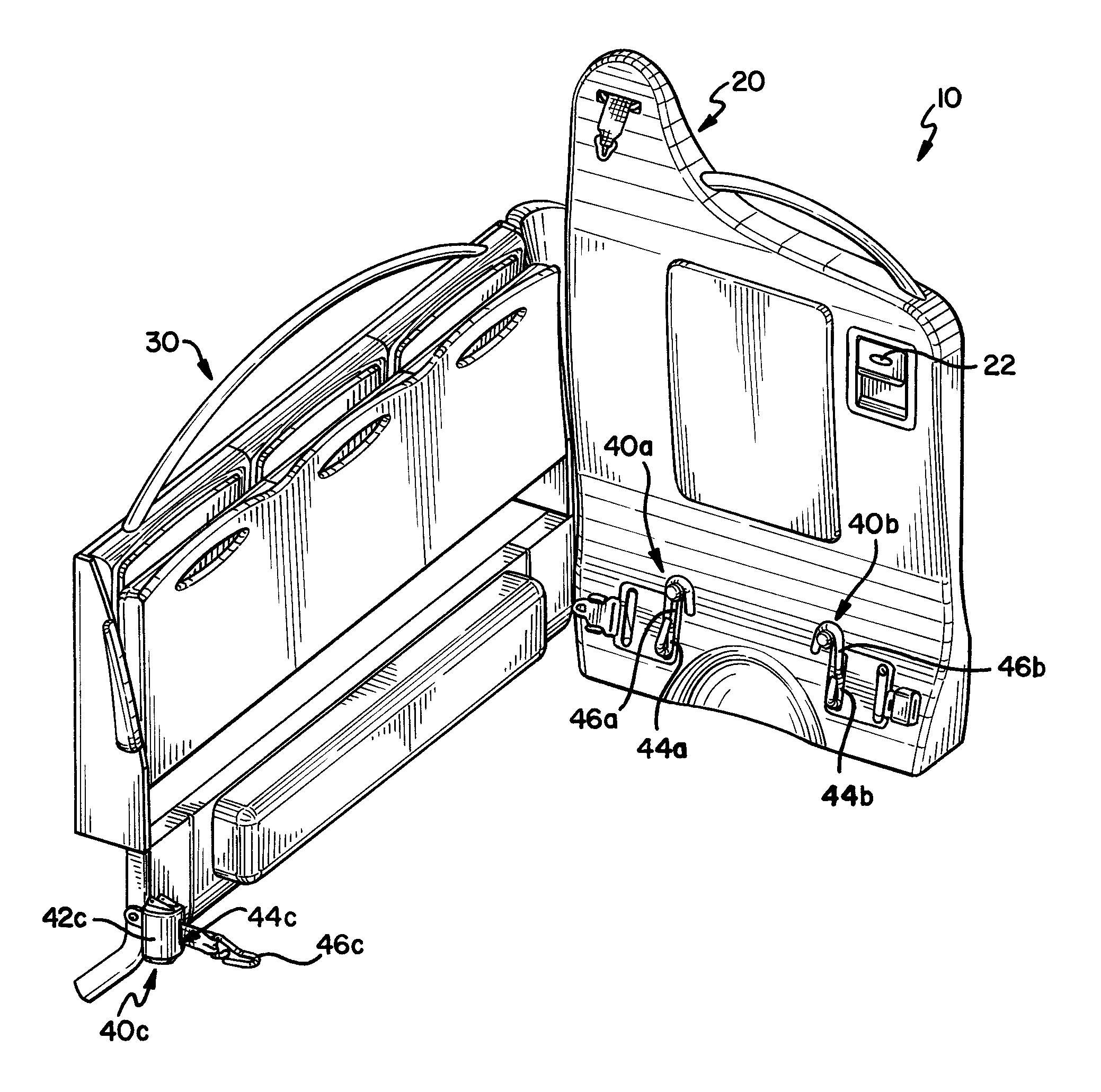
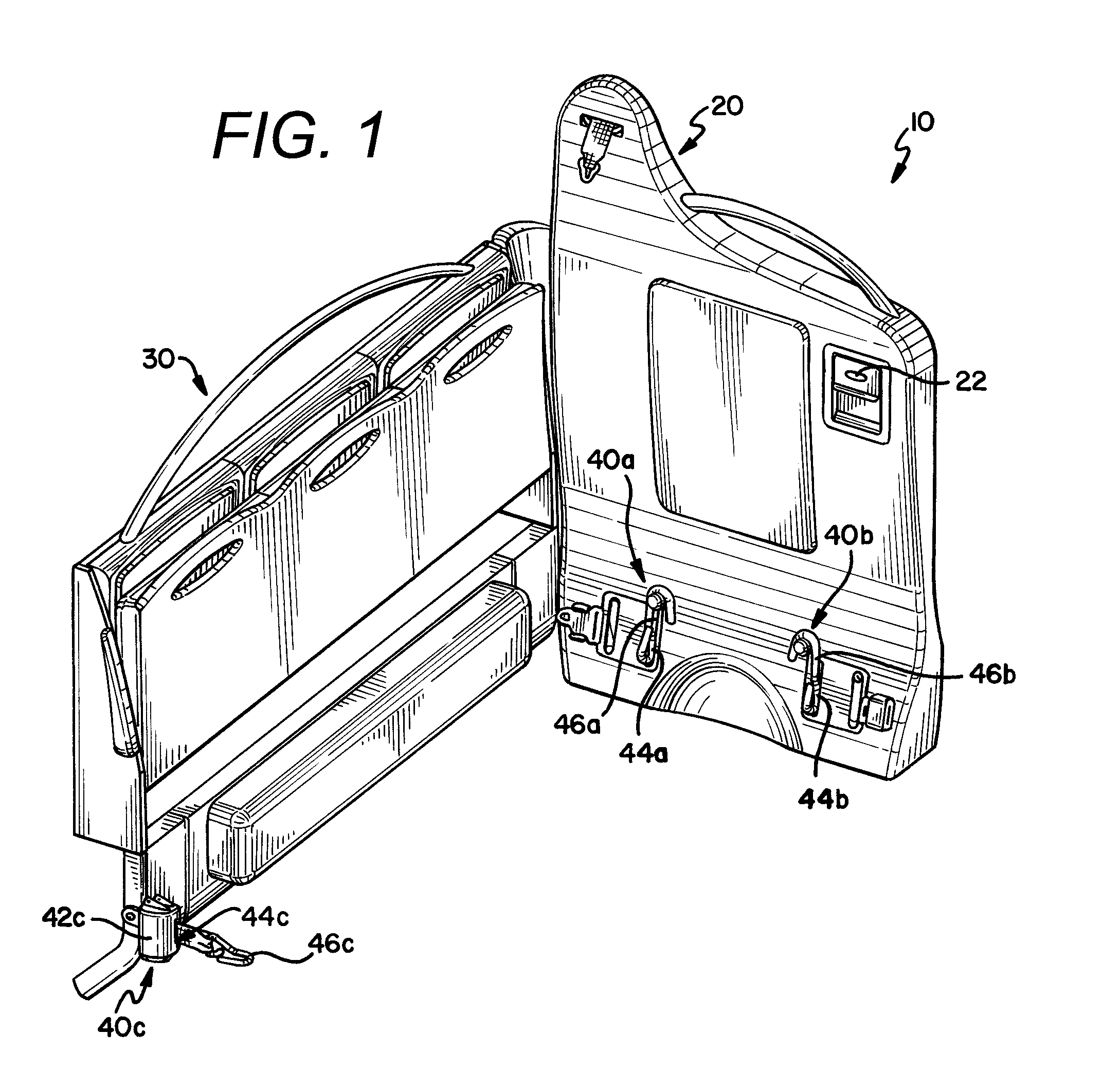
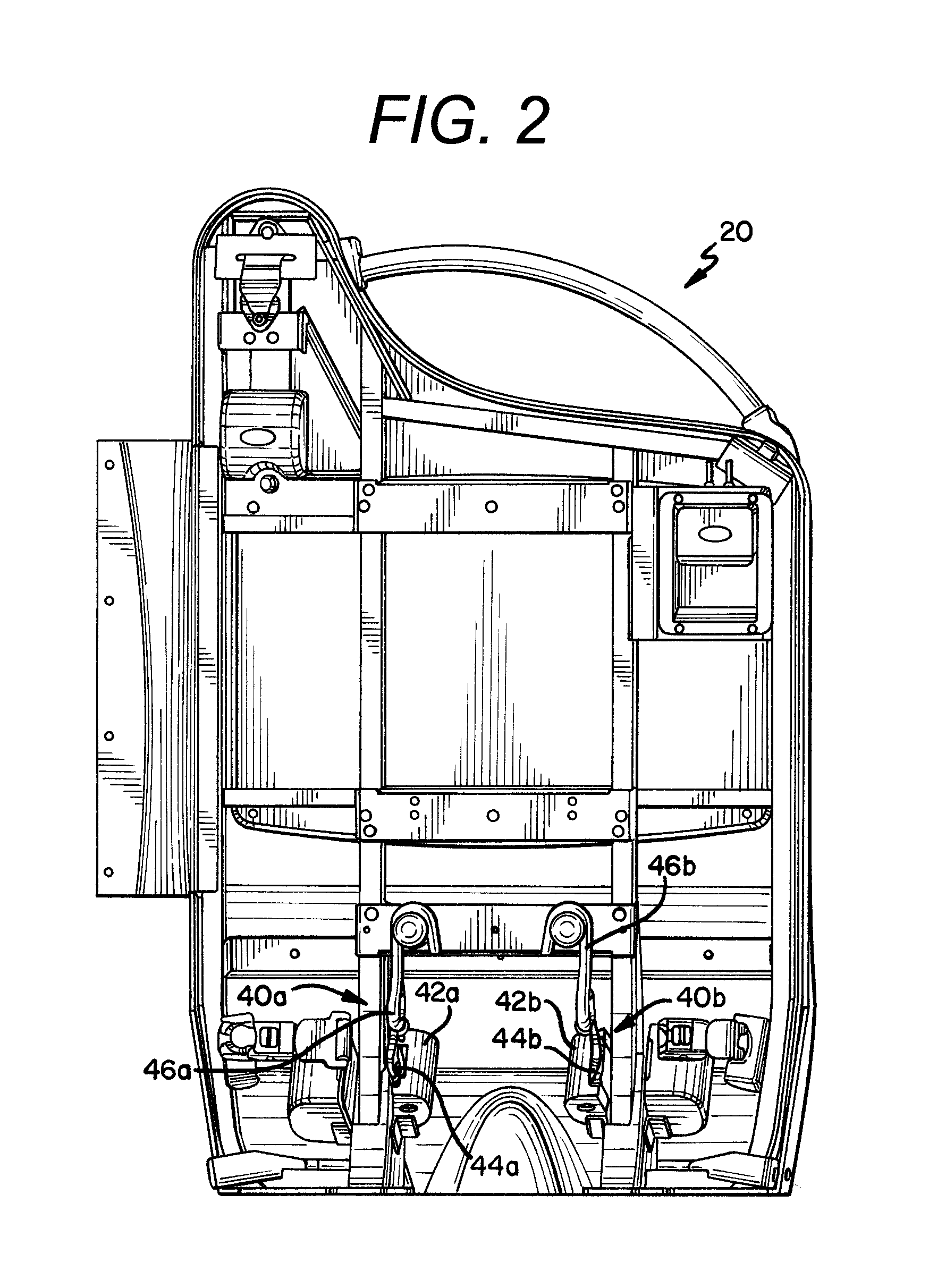
[0044]In the first embodiment, the wheelchair securement system 10 is best characterized as a drop-in system for a vehicle which is fully-equipped to secure a wheelchair and its passenger in a forward facing orientation (i.e., with respect to the direction of travel of the vehicle). In this orientation, the barrier module 20 is forward-facing (i.e., positioned rearward of the side-wall module 30 in the vehicle) and secures the wheelchair at two attachment points at the rear of the wheelchair. Although shown in a configuration suitable for installation adjacent a right side wall of a vehicle, the system 10 could be configured as a mirror image of the shown configuration for installation adjacent a left side wall of the vehicle. The side-wall module 30 is positioned adjacent to a wall of the vehicle and secures the wheelchair at a single attachment point at the front of the wheelchair. The barrier module 20 and side-wall module 30, through the use of three points of attachment to the ...
second embodiment
[0054]In the shown embodiment, it is contemplated that the side barrier 34 would have resilient properties, wherein it would have some give, but still provide firm support for the wheelchair. In an alternative embodiment, the side barrier 34 could be biased outward using, for example, a spring that pushes the side barrier 34 outward. When the front restraint 40c was hooked up and would pull the chair in, the springs would provide an opposing force to stabilize the chair. As discussed below at least in the context of the second embodiment, the side barrier 34 could also be mechanized or inflatable, wherein it is movable to positively contact the wheelchair and induce pre-tension into the securement assemblies 40a, 40b, 40c.
[0055]With reference now to FIGS. 3-4, a second embodiment of a wheelchair securement system 110 is shown. Like the first embodiment, the second embodiment includes a barrier module 120 and a side-wall module 130 that are substantially similar to those described i...
sixth embodiment
[0074]As with some of the previous embodiments, the barrier module 620 includes a remote control device with a release latch (or paddle handle) 622 for releasing one or more of the securement assemblies 640a, 640b, 640c, such as any one of the systems described in U.S. provisional patent application Ser. Nos. 60 / 705,452, U.S. provisional patent application No. 60 / 618,572, U.S. patent application Ser. No. 11 / 252,326, and / or PCT patent application no. PCT / US06 / 30085. In the shown embodiment, paddle handle 622 releases the locking mechanisms of retractors 642a, 642b for a predetermined amount of time, which is sufficient for the vehicle operator to engage / release the fasteners 646a, 646b with / from the wheelchair.
[0075]Proper restraint of a wheelchair in the sixth embodiment of the system 610 can be achieved using the following steps. First, the side seat should be placed and locked in the folded, upward position. Second, the wheelchair is moved into position with the back of the passen...
PUM
 Abstract
Description
Claims
Application Information
 - R&D
- Intellectual Property
- Life Sciences
- Materials
- Tech Scout
- Unparalleled Data Quality
- Higher Quality Content
- 60% Fewer Hallucinations
Browse by: Latest US Patents, China's latest patents, Technical Efficacy Thesaurus, Application Domain, Technology Topic, Popular Technical Reports.
© 2025 PatSnap. All rights reserved.Legal|Privacy policy|Modern Slavery Act Transparency Statement|Sitemap|About US| Contact US: help@patsnap.com


