CO2 recovery apparatus and CO2 recovery method

a co2 recovery and co2 technology, applied in liquid degasification, separation of dispersed particles, separation processes, etc., can solve the problem of high heat loss of methods, and achieve the effect of dramatically reducing the amount of steam supplied into the reheater

Active Publication Date: 2013-04-09
THE KANSAI ELECTRIC POWER CO +1
View PDF30 Cites 77 Cited by
  • Summary
  • Abstract
  • Description
  • Claims
  • Application Information

AI Technical Summary

Benefits of technology

[0028]According to the present invention, the heat balance of the entire system can be taken into account. As a result, the amount of steam supplied into the reheater can be dramatically reduced.

Problems solved by technology

Disadvantageously, this method has a high heat loss, because steam is released out of the steam system by accompanying the CO2 gas 26a that is brought out of the regenerator 18.

Method used


Image

  • CO2 recovery apparatus and CO2 recovery method
  • CO2 recovery apparatus and CO2 recovery method
  • CO2 recovery apparatus and CO2 recovery method

Examples


example 1

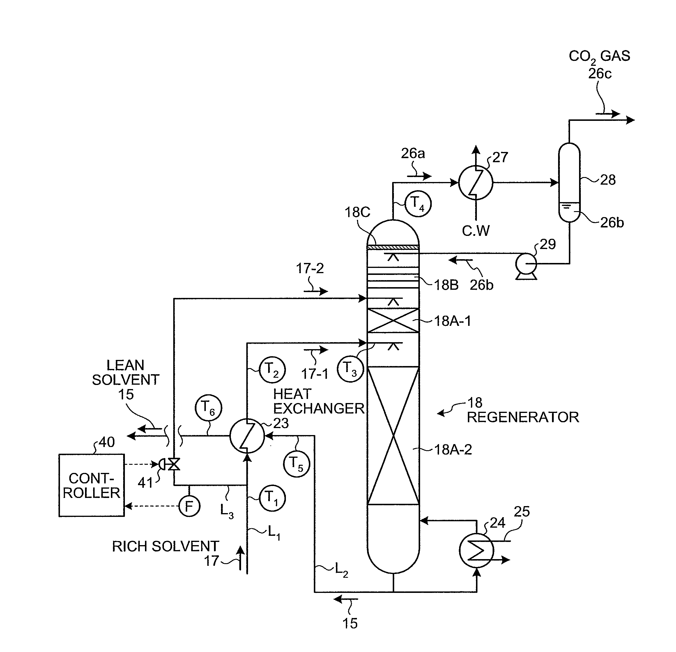
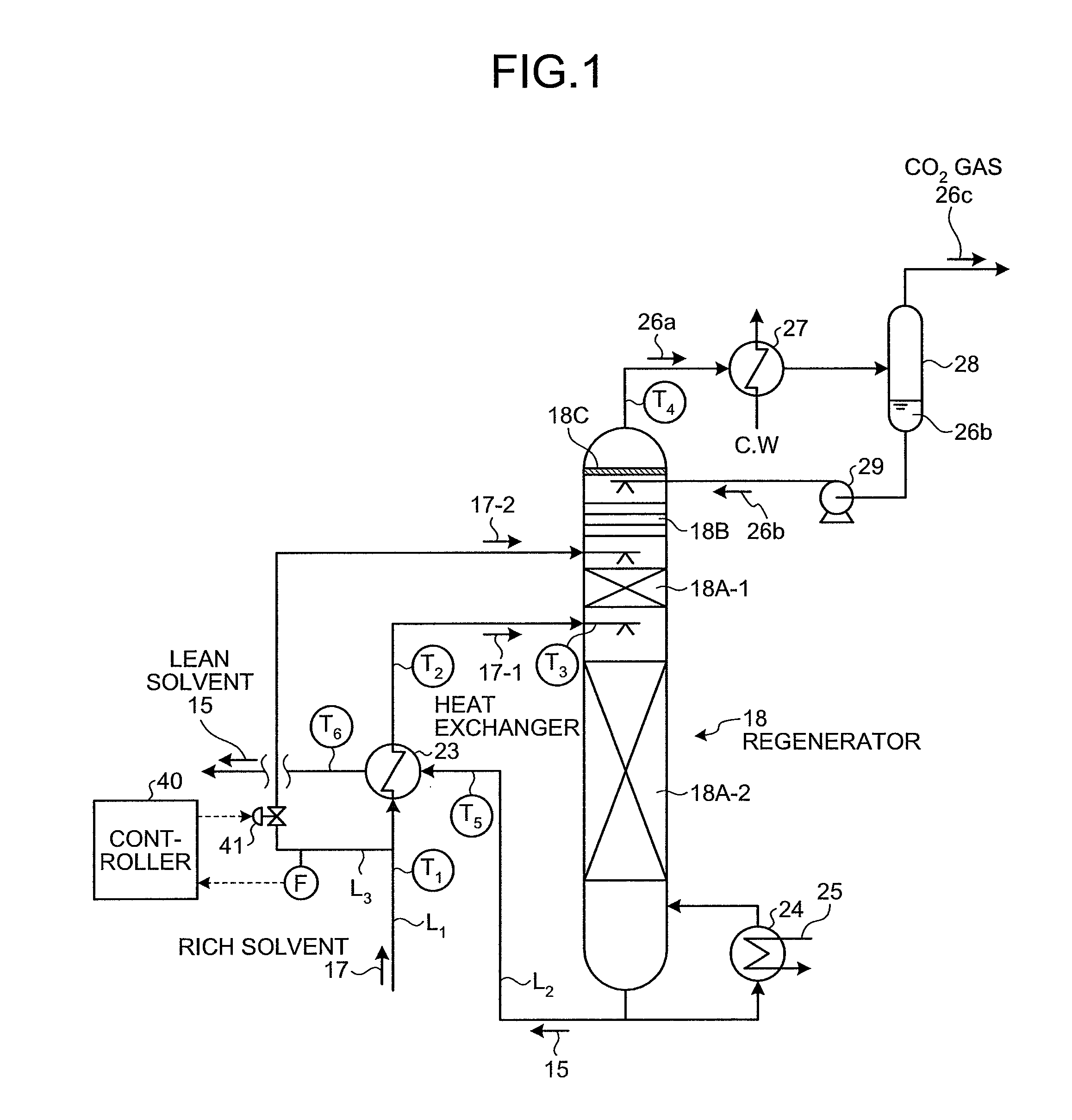
[0038]A CO2 recovery unit according to a first embodiment of the present invention will now be explained with reference to FIG. 1.

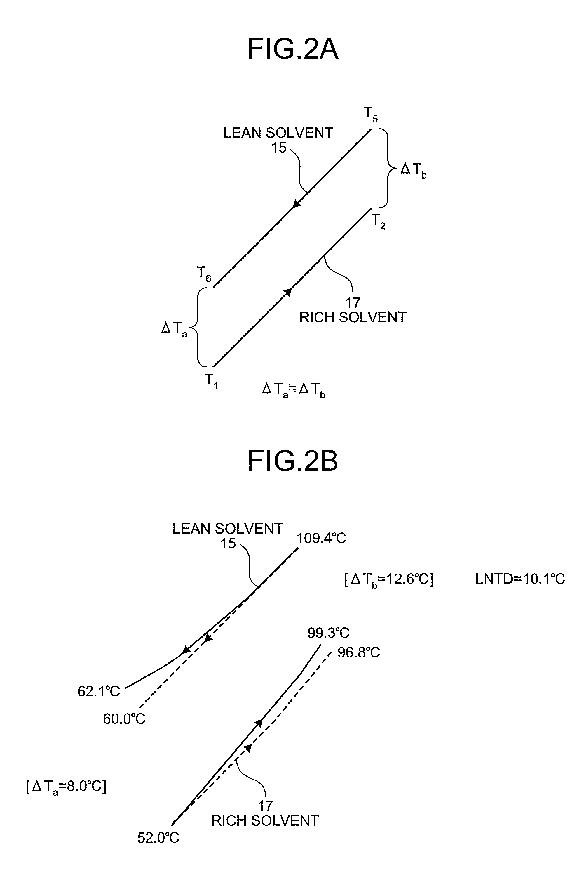
[0039]FIG. 1 is a schematic of a structure of the CO2 recovery unit according to the first embodiment. FIG. 2A is a schematic of a heat balance of a lean solvent and a rich solvent in a heat exchanger included in the CO2 recovery unit according to the first embodiment. FIG. 2B is a schematic of a test example of the heat balance of the lean solvent and the rich solvent in the heat exchanger of the CO2 recovery unit according to the first embodiment. In FIG. 1, the same structures as those in the CO2 recovery unit shown in FIG. 5 are given the same reference signs, and redundant explanations thereof are omitted herein. FIG. 1 depicts the CO2 regenerator 18 included in the CO2 recovery unit 100 explained above.

[0040]As shown in FIG. 1, the CO2 recovery unit according to the first embodiment includes: a CO2 absorber (not shown) that brings flue gas containin...

example 2

[0064]A CO2 recovery unit according to a second embodiment of the present invention will now be explained with reference to FIGS. 3A and 3B.

[0065]FIGS. 3A and 3B are schematics of structures of the CO2 recovery unit according to the second embodiment. In these drawings, the same structures as those in the CO2 recovery unit shown in FIG. 1 are given the same references signs, and redundant explanations thereof are omitted herein.

[0066]As shown inFIG. 3A, the CO2 recovery unit according to the second embodiment includes a first heat exchanging unit 18D that allows the rich solvent portion 17-2 bypassed and introduced from the top of the regenerator 18 to exchange heat at the top of the regenerator.

[0067]In the first heat exchanging unit 18D, the rich solvent portion 17-2 that is temporarily is brought into the regenerator 18 is heated by way of rising steam, having the temperature thereof (T7) increased by the time of being released into the regenerator 18.

[0068]Therefore, the amount ...

example 3

[0071]A CO2 recovery unit according to a third embodiment of the present invention will now be explained with reference to FIGS. 4A and 4B.

[0072]FIGS. 4A and 4B are schematics of structures of the CO2 recovery unit according to the third embodiment. In these drawings, the same structures as those in the CO2 recovery unit shown in FIG. 1 are given the same references signs, and redundant explanations thereof are omitted herein.

[0073]As shown in FIG. 4A, the CO2 recovery unit according to the third embodiment includes a second heat exchanging unit 18E that allows the CO2 gas 26a accompanying steam, taken out from the regenerator 18, to exchange heat with the bypassed rich solvent portion 17-2.

[0074]Because the rich solvent portion 17-2 that is before being supplied into the regenerator 18 exchanges heat with the CO2 gas 26a accompanying steam that is to be released out, the rich solvent portion 17-2 is heated by steam, having the temperature thereof (T8) increased, by the time the ric...


PUM

PropertyMeasurementUnit
temperaturesaaaaaaaaaa
temperatureaaaaaaaaaa

Abstract

Provided are a CO2 absorber that reduces CO2 contained in flue gas; a regenerator that reduces CO2 contained in rich solvent absorbing CO2 to regenerate the rich solvent, so that lean solvent having the CO2 reduced in the regenerator is reused in the CO2 absorber; a heat exchanger that allows the rich solvent to exchange heat with the lean solvent; and a controller that controls to extract rich solvent portion that is part of the rich solvent, to allow the rich solvent portion to by pass the heat exchanger, and to be supplied into the top of the regenerator without exchanging heat so as to minimize a sum of an enthalpy that is taken out of the regenerator as CO2 gas accompanying steam and an enthalpy of the lean solvent after heat exchange with the rich solvent in the heat exchanger.

Description

TECHNICAL FIELD[0001]The present invention relates to a CO2 recovery unit and a CO2 recovery method that can dramatically reduce the amount of energy used in regenerating a CO2 absorbent in a CO2 recovery process.BACKGROUND ART[0002]It has come to be pointed out that one of the causes of the global warming is a greenhouse effect of CO2, and it has became an urgent task, also internationally, to provide a countermeasure for CO2 to protect the global environment against the warming. CO2 is generated by any human activities combusting fossil fuels, and there are increasing demands for suppressing CO2 emissions. Along with such an increasing demand, researchers are energetically investigating a method for reducing and recovering CO2 included in flue gas, to apply in a power plant that consumes a large amount of fossil fuels, such as a thermal plant. In such a method, flue gas emitted from a steam generator is brought into contact with an amine-based CO2 absorbent to allow such absorbent...

Claims


Application Information

Patent Timeline
Patent Type & Authority Patents(United States)
IPC IPC(8): B01D53/14C01B32/50
CPCB01D53/1412B01D53/1425B01D53/1475B01D53/62B01D2251/80B01D2257/504Y02C10/06B01D53/77Y02C20/40
Inventor IIJIMA, MASAKIOGURA, KOUKITATSUMI, MASAHIKOYAGI, YASUYUKI
Owner THE KANSAI ELECTRIC POWER CO
Why Eureka
Try Eureka