
Cleaning method for foggy images

a cleaning method and image technology, applied in image enhancement, image analysis, instruments, etc., can solve the problems of obstructing traffic control systems, image unrecognizable, and complex physical processes and conditions for fog formation

Active Publication Date: 2013-04-09
HUPER LAB
View PDF3 Cites 11 Cited by
  • Summary
  • Abstract
  • Description
  • Claims
  • Application Information

AI Technical Summary

Benefits of technology

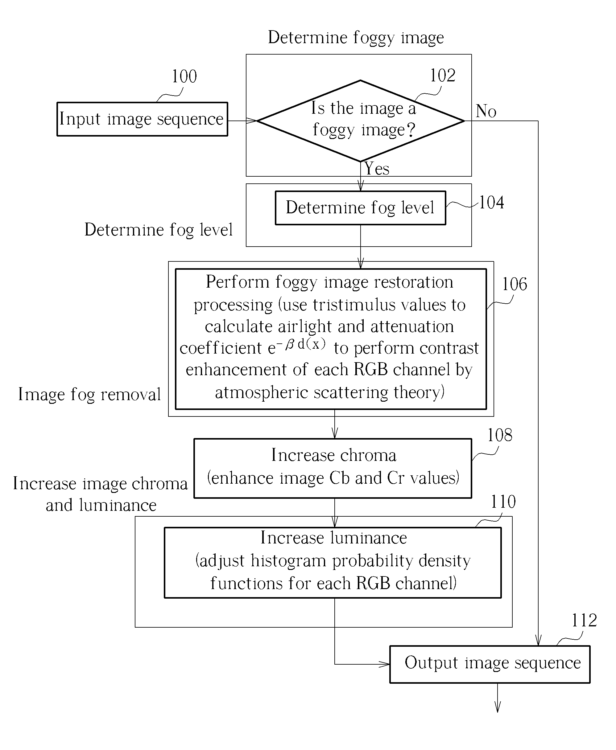
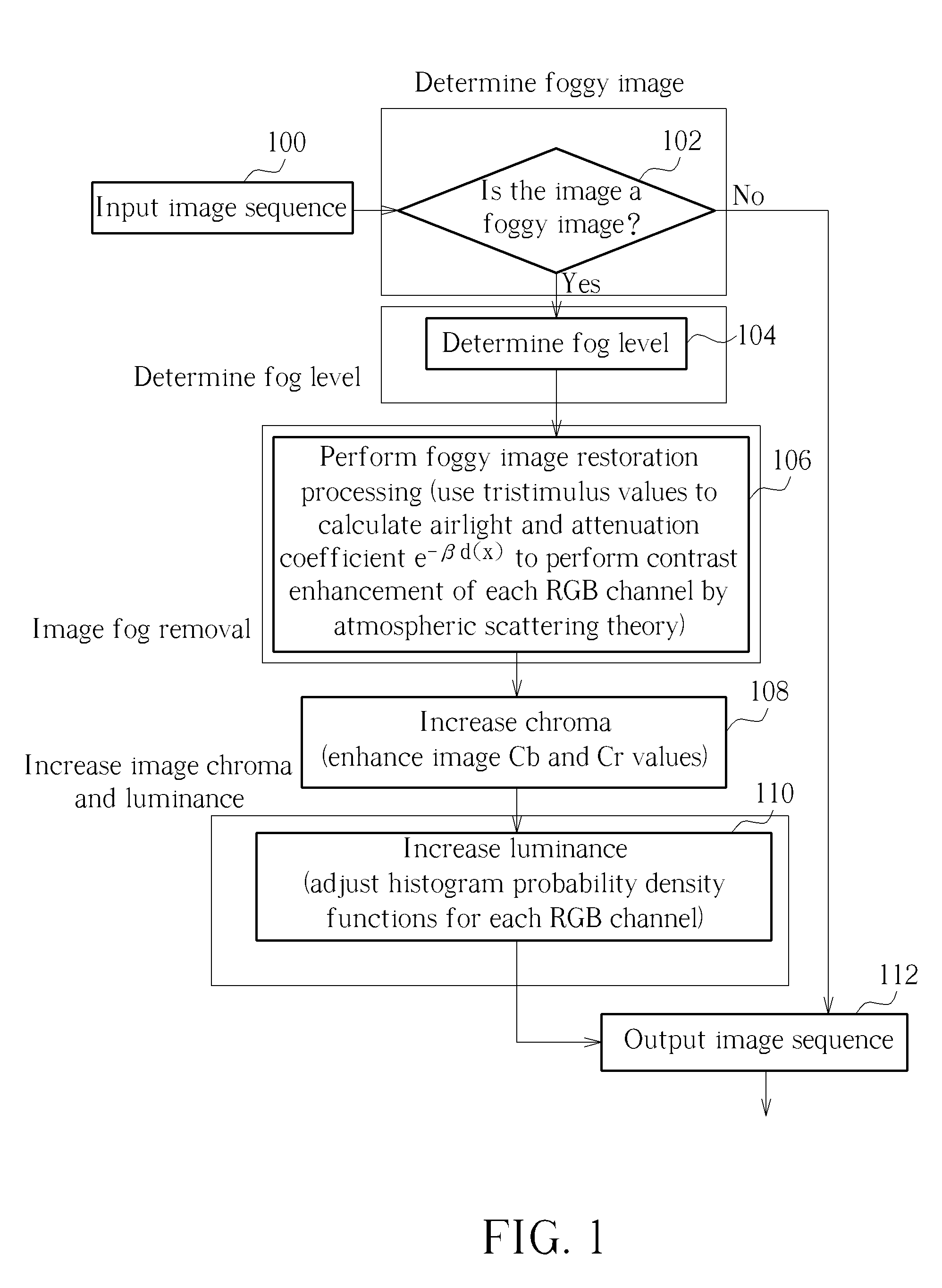
[0028]According to another embodiment, a cleaning method for foggy images comprises using a stimulus value of a light chromaticity (LC) of an input image to generate an airlight luminance, using red-green-blue (RGB) tristimulus values of the input image to generate an attenuation coefficient, using the airlight luminance and the attenuation coefficient to recover the input image for generating a primary reduction image, transforming the primary reduction image into YCbCr color model and boosting values of Cb and Cr values of the primary reduction image to enhance chromaticity of the primary reduction image, redistributing weighting of a probability density function of an RGB gray level histogram after enhancing chromaticity of the primary reduction image, and enhancing luminance of the primary reduction image through histogram equalization after enhancing chromaticity of the primary reduction image to generate a final reduction image.

Problems solved by technology

However, due to the influence of foggy conditions brought about by seasonal weather, because visibility is reduced when computer visualization is utilized for traffic monitoring, images captured may be unclear, making the images unrecognizable, and keeping the computer visualization application from being able to obtain accurate color information during processing.
However, the reasons for cooling are different in fog and clouds.
The physical processes and conditions for forming fog are also very complex.
Fog affects visibility in the surrounding environment, obstructing traffic control systems.
For example, air traffic control towers, road traffic monitors, and harbor ship controllers are all affected by fog, which increases danger.
In addition to traffic control, equipment that relies on the aid of monitoring systems is also affected, which greatly reduces the value of image monitoring systems.
However, this technique requires two images of the environment taken at two different times to perform correction on the image that is already affected by fog.
The user first needs to obtain background information for the two images, which makes the method impractical for use with processing of unknown environments.
However, calculating appropriate values for the scattering coefficient β and the depth d is difficult.
Thus, a large number of calculations are required, making the method impractical for real-time applications, not to mention that the method introduces an image chromaticity bias.
The method requires approximately five to seven minutes to restore a 640×480 pixel image, making the method unsuitable for real-time applications.
However, this method is ineffective when no road markings are available, e.g. when traveling on the water.
Further, a scene captured by the automobile camera will change over time.
If the method were used in a color camera, the RGB color information will change as the distance changes, causing incongruity of the colors of the image, making the method unsuitable for use in color cameras.
If the scene changes, the distance obtained may not lead to an accurate extinction coefficient β. When traveling on the water, the camera is unable to select a reference object analogous to the preceding vehicle due to heavy waves.
Thus, this method would be ineffective if applied to a ship with a camera mounted thereon.
Thus, if only one image is available, this method is unusable.
However, the method requires 35 seconds to process one image, making the method unusable in real-time monitoring systems.
However, this method is only directed at one particular region of the image, and is not directed to classification of the entire image.

Method used


Image

  • Cleaning method for foggy images
  • Cleaning method for foggy images
  • Cleaning method for foggy images

Examples


Embodiment Construction

[0040]Please refer to FIG. 1, which is a flowchart of a cleaning method according to one embodiment. First, it is determined whether the image is a foggy image. If so, a fog level of the image is calculated. Then, color change of the foggy image is analyzed, and the influence of the fog is removed. Foggy images may have insufficient color, so that the image may have a dark bias or a color bias after removing the fog. Thus, chromaticity is increased in the image after fog removal. Then, visibility of the image is increased. In this way, a foggy image can be cleaned through use of the cleaning method.

[0041]The method may be applied in specific transportation domains, e.g. for ships entering or leaving a port, for automobiles travelling along roads, and in airport control towers for planes taking off or landing, to increase safety in low-visibility environments. Additionally, the cleaning method may be utilized in pre-processing stages of intelligent transportation digital video record...


PUM


Abstract

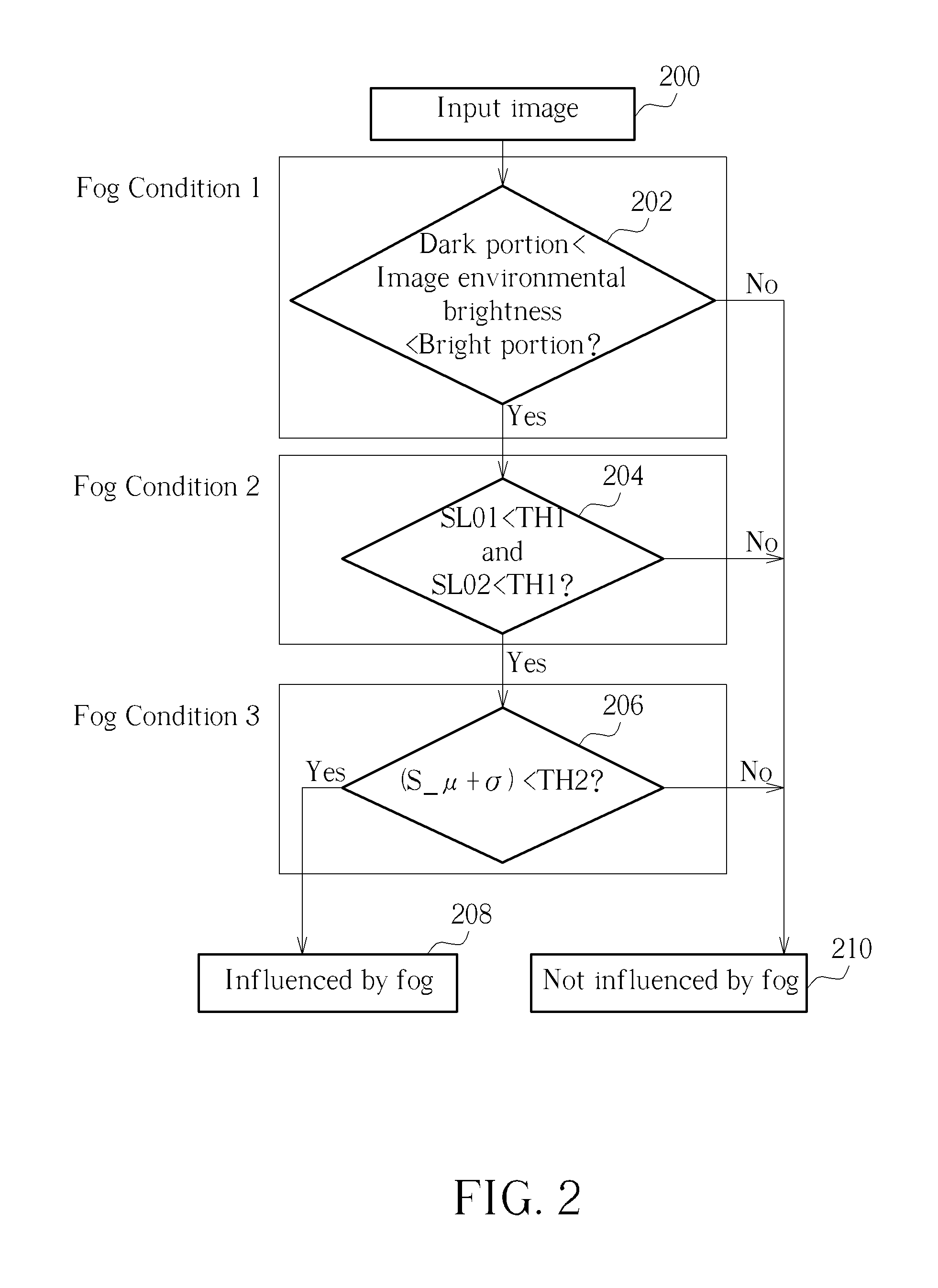
Determining if an input image is a foggy image includes determining an average luminance gray level of the input image, performing Sobel image processing on the input image to generate a Sobel image of the input image when the average luminance gray level of the input image is between a first image average luminance and a second image average luminance, determining a first normalization value and a second normalization value of the input image, determining a mean value and a standard deviation of the Sobel image when the first normalization value and the second normalization value are less than a first threshold value, and determining the input image as a foggy image when a sum of the mean value and the standard deviation is less than a second threshold value.

Description

BACKGROUND OF THE INVENTION[0001]1. Field of the Invention[0002]The present invention relates to cleaning methods for foggy images, and more particularly to a cleaning method for foggy images based on atmospheric scattering theory and color analysis.[0003]2. Description of the Prior Art[0004]In recent years, economic growth has spurred an increased interest in transportation issues. As roadway monitoring systems adopt computer visualization and image processing techniques more widely, traffic volume is steadily increasing, leading to research and development of all types of transportation-related technologies. Among a great volume of traffic-monitoring research, an Intelligent Transportation System (ITS) is one method utilized to solve traffic problems. ITS incorporates communications, control, electronics, and information technologies to put limited traffic data to its greatest use, so as to improve transportation safety, improve quality of life, and enhance economic competitivenes...

Claims


Application Information

Patent Timeline
Patent Type & Authority Patents(United States)
IPC IPC(8): G06K9/40G06K9/00
CPCG06T5/003G06T5/20G06T5/40G06T2207/30236G06T2207/10024G06T2207/20076G06T2207/10016
Inventor CHEN, CHAO-HOTSAI, WEN-WEI
Owner HUPER LAB
Learn More