Image processing device, image processing method, and program
a technology of image processing and image processing, applied in the field of image correction processing, can solve the problems of pain to watch a video that was taken, the inability of the operator to hold the video camera in a horizontal orientation, and the inability to determine the reference angle, so as to achieve high accuracy and reduce the processing load required for performing the detection algorithm. , the effect of high-quality pictures
- Summary
- Abstract
- Description
- Claims
- Application Information
AI Technical Summary
Benefits of technology
Problems solved by technology
Method used
Image
Examples
embodiment 1
(Embodiment 1)
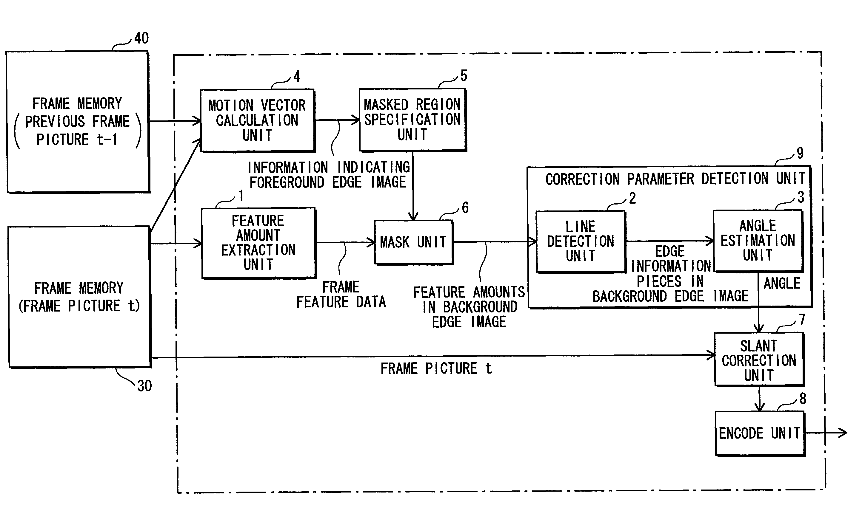
[0095]As one of many possible embodiments of the present invention, the present embodiment allows detecting, from current frame picture data, a slant as a correction parameter, and performing image processing on the current frame picture in accordance with the correction parameter. One example of such image processing is a rotation transformation.
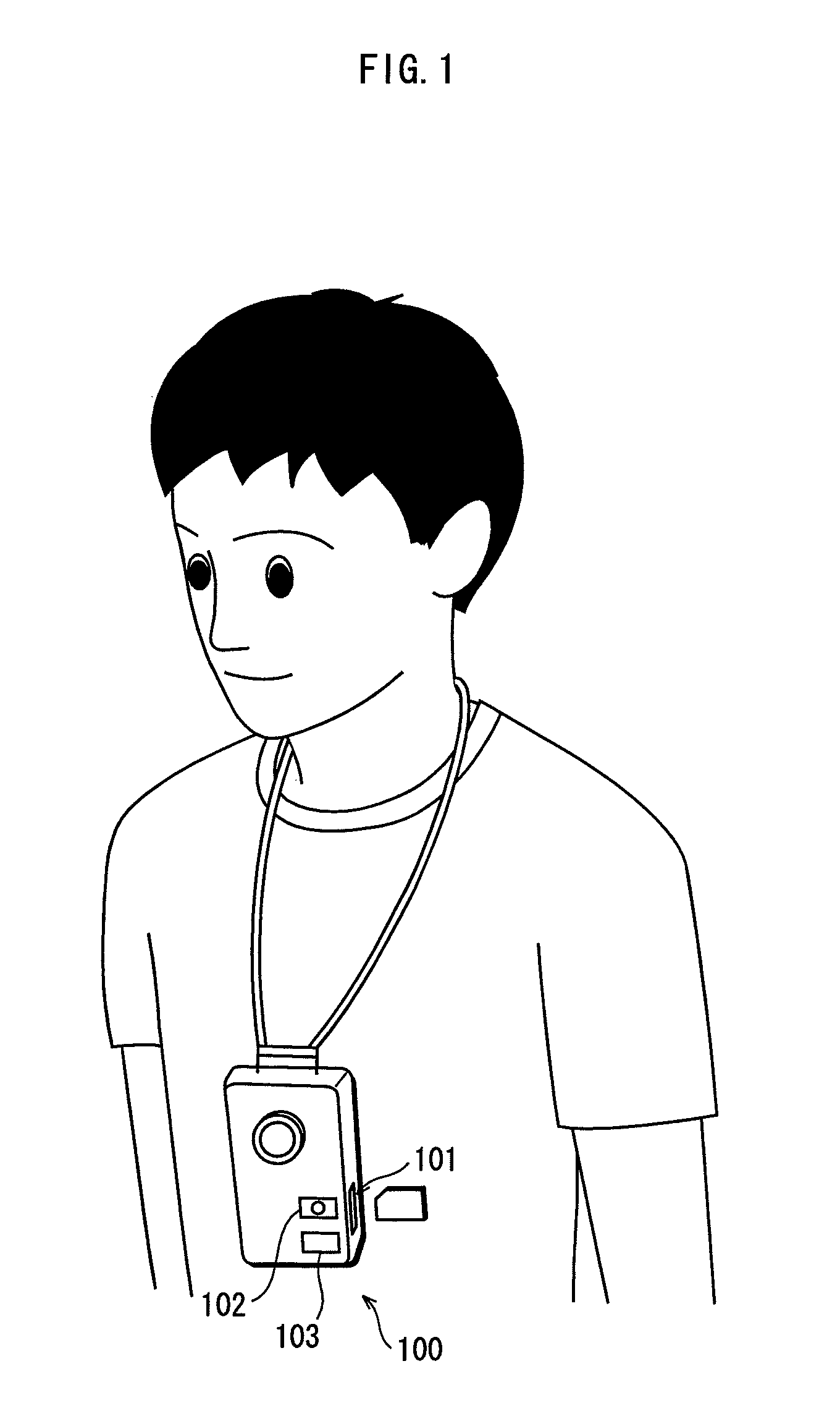
[0096]FIG. 1 shows a usage example of an imaging apparatus to which the image processing device of the present invention is applied. As shown in FIG. 1, a user uses a neck strap to wear a video camera 100 in which the image processing device of the present invention is provided, so that he can take a video by handling the video camera 100 in a hands-free manner. The casing of the video camera 100 has (i) a card slot through which a semiconductor memory card that would serve as a recording medium can be inserted / ejected, (ii) a record button 102 to receive an operation to start imaging processing, and (iii) a stop button 103 to...
modification to embodiment 1
(Modification to Embodiment 1)
[0157]The constituent elements explained in Embodiment 1, such as the masked region specification unit, the mask unit, the line detection unit, the angle estimation unit, and the slant correction unit, can be realized as a program that makes MPU execute processing procedures shown in flowcharts of FIGS. 10 and 11.
[0158]FIG. 10 is a flowchart showing processing procedures for separating a foreground edge image from a frame feature data. FIG. 11 is a flowchart showing processing procedures from feature amount extraction to angle estimation. Referring to the flowchart of FIG. 10, processing of Step S2 is executed by the motion vector calculation unit 4, and processing of Steps S3 to S12 is executed by the masked region specification unit 5. Referring to the flowchart of FIG. 11, processing of Steps S23 to S27 is executed by the mask unit 6, processing of Step S28 is executed by the line detection unit 2, and processing of Steps S29 to S31 is executed by th...
embodiment 2
(Embodiment 2)
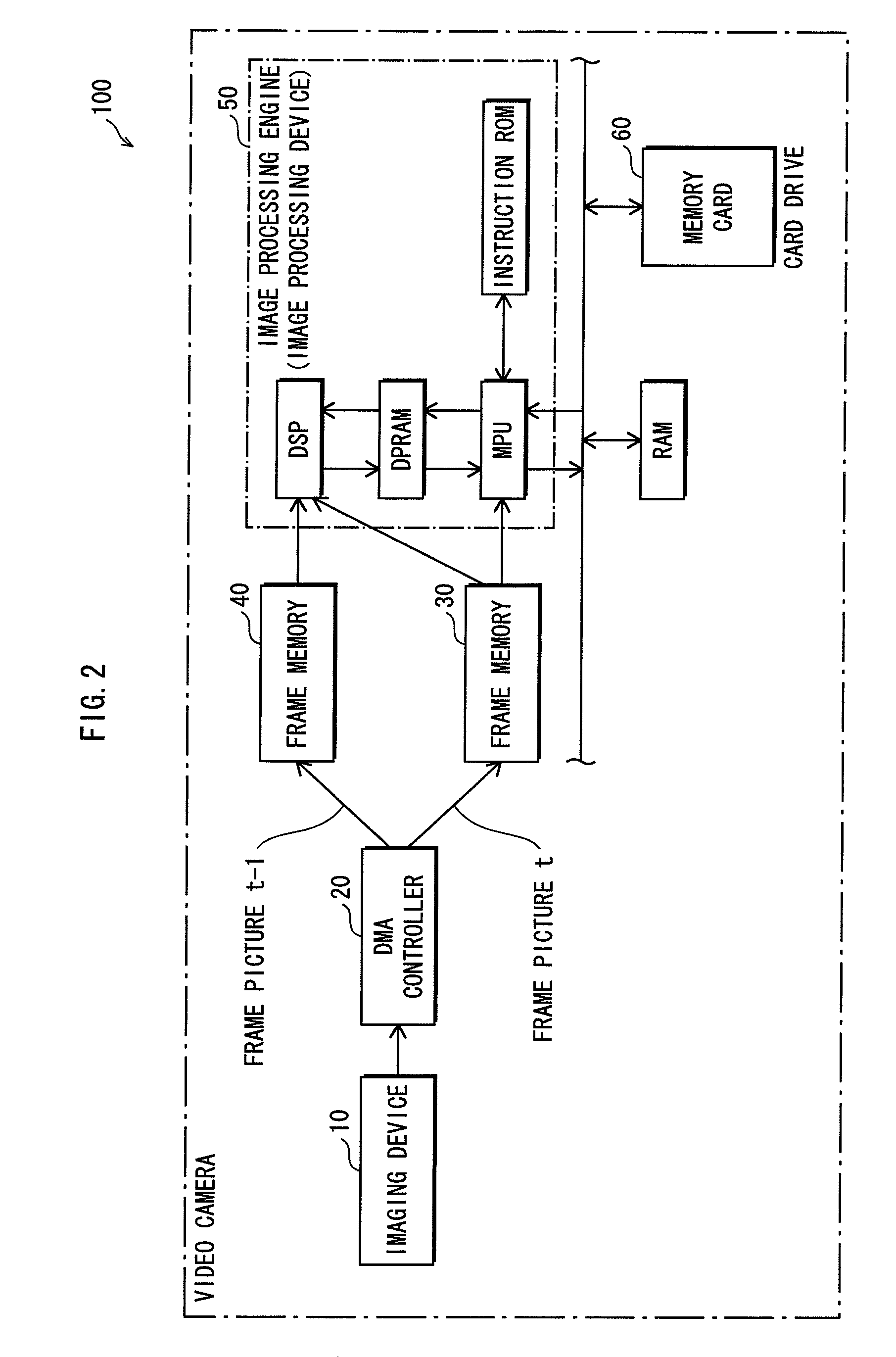
[0169]FIG. 12 shows a hardware structure of an image processing device pertaining to Embodiment 2 of the present invention. Some constituent elements shown in FIG. 12 are configured the same as their counterparts in FIG. 11; these constituents elements are labeled the same reference numbers as their counterparts in FIG. 12, and the descriptions thereof are omitted.
[0170]As shown in FIG. 12, Embodiment 2 of the present invention is different from Embodiment 1 of the same in that (i) there is an additional constituent element, i.e., an inertial sensor 70 that can detect angular components associated with angles around a roll axis, and (ii) the line detection unit 2 utilizes an output from the sensor 70. Examples of such an inertial sensor 70, which can detect the angular components associated with the angles around the roll axis, include an acceleration sensor and a gyroscope.
[0171]The inertial sensor 70 obtains the slant angle around the roll axis which was measured at ...
PUM
 Abstract
Description
Claims
Application Information
 - R&D
- Intellectual Property
- Life Sciences
- Materials
- Tech Scout
- Unparalleled Data Quality
- Higher Quality Content
- 60% Fewer Hallucinations
Browse by: Latest US Patents, China's latest patents, Technical Efficacy Thesaurus, Application Domain, Technology Topic, Popular Technical Reports.
© 2025 PatSnap. All rights reserved.Legal|Privacy policy|Modern Slavery Act Transparency Statement|Sitemap|About US| Contact US: help@patsnap.com


