Internal gear manufacturing method and metallic glass internal gear manufactured thereby

a manufacturing method and internal gear technology, applied in gearing, gearing, foundry patterns, etc., can solve the problems of insufficient production capacity to manufacture a large number of internal gears, irremovable confinement of the core within, etc., to achieve high-precision internal gear manufacturing, accurate formation of external gears, good demoldability

Inactive Publication Date: 2013-04-16
NAMIKI PRECISION JEWEL CO LTD +1
View PDF36 Cites 21 Cited by
  • Summary
  • Abstract
  • Description
  • Claims
  • Application Information

AI Technical Summary

Benefits of technology

[0005]Proposed with a focus on the above problems, the present invention intends to provide an internal gear manufacturing method capable of manufacturing time reduction, productivity enhancement, and easy core removal, and a metallic glass internal gear manufactured thereby.
[0014]The present invention provides an internal gear manufacturing method capable of manufacturing time reduction and easy core removal, and a metallic glass internal gear manufactured thereby.

Problems solved by technology

The method disclosed in International Publication Pamphlet No. 2005 / 024274 is capable of high-precision manufacturing of a metallic glass internal gear with high hardness, high strength, and other advantages, but only in a one-at-a-time fashion, and hence is not productive enough to manufacture a large number of internal gears.
Additionally and inconveniently, a molded article obtained by injection-molding undergoes overall cooling followed by thermal shrinkage, thereby irremovably confining a core within.

Method used


Image

  • Internal gear manufacturing method and metallic glass internal gear manufactured thereby
  • Internal gear manufacturing method and metallic glass internal gear manufactured thereby
  • Internal gear manufacturing method and metallic glass internal gear manufactured thereby

Examples


Embodiment Construction

[0021]Descriptions are made below of the best modes for carrying out the present invention with reference to drawings appended hereto.

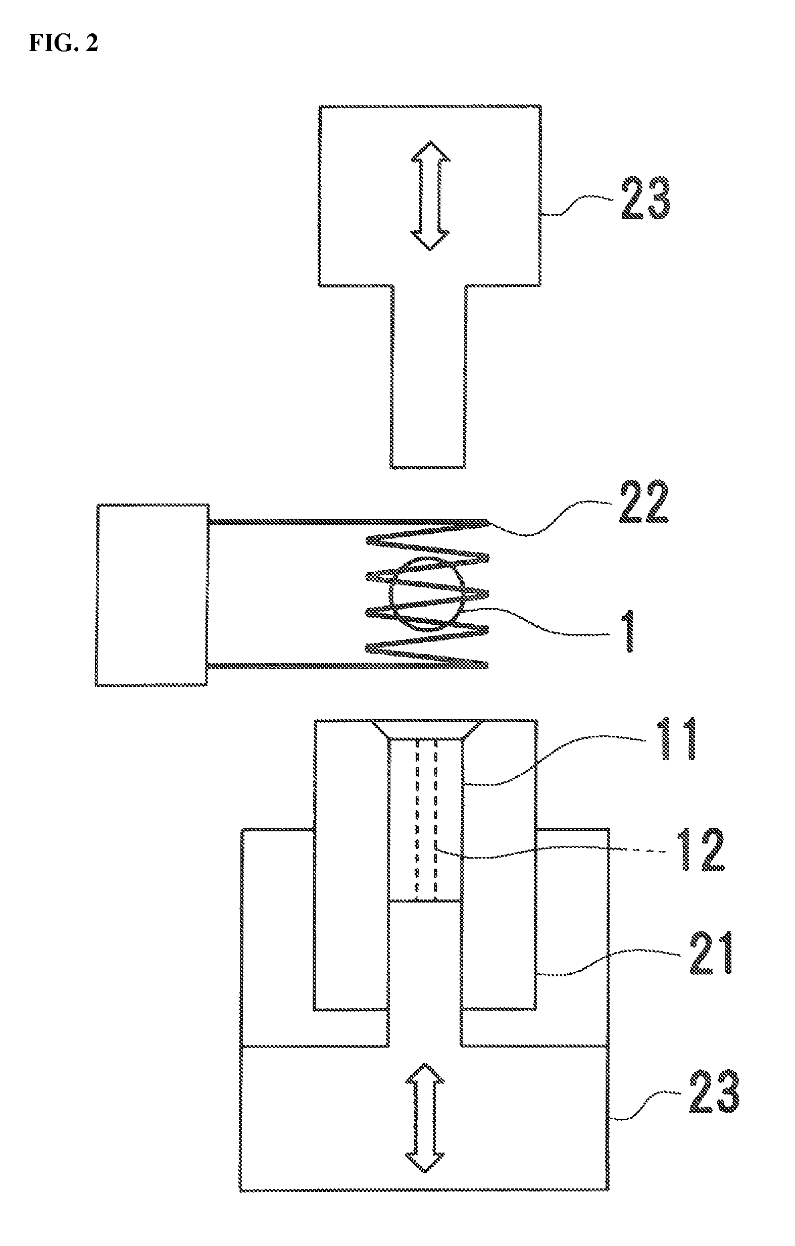
[0022]FIG. 1 to FIG. 3 show embodiments of the internal gear manufacturing method according to the present invention and a metallic glass internal gear manufactured thereby.

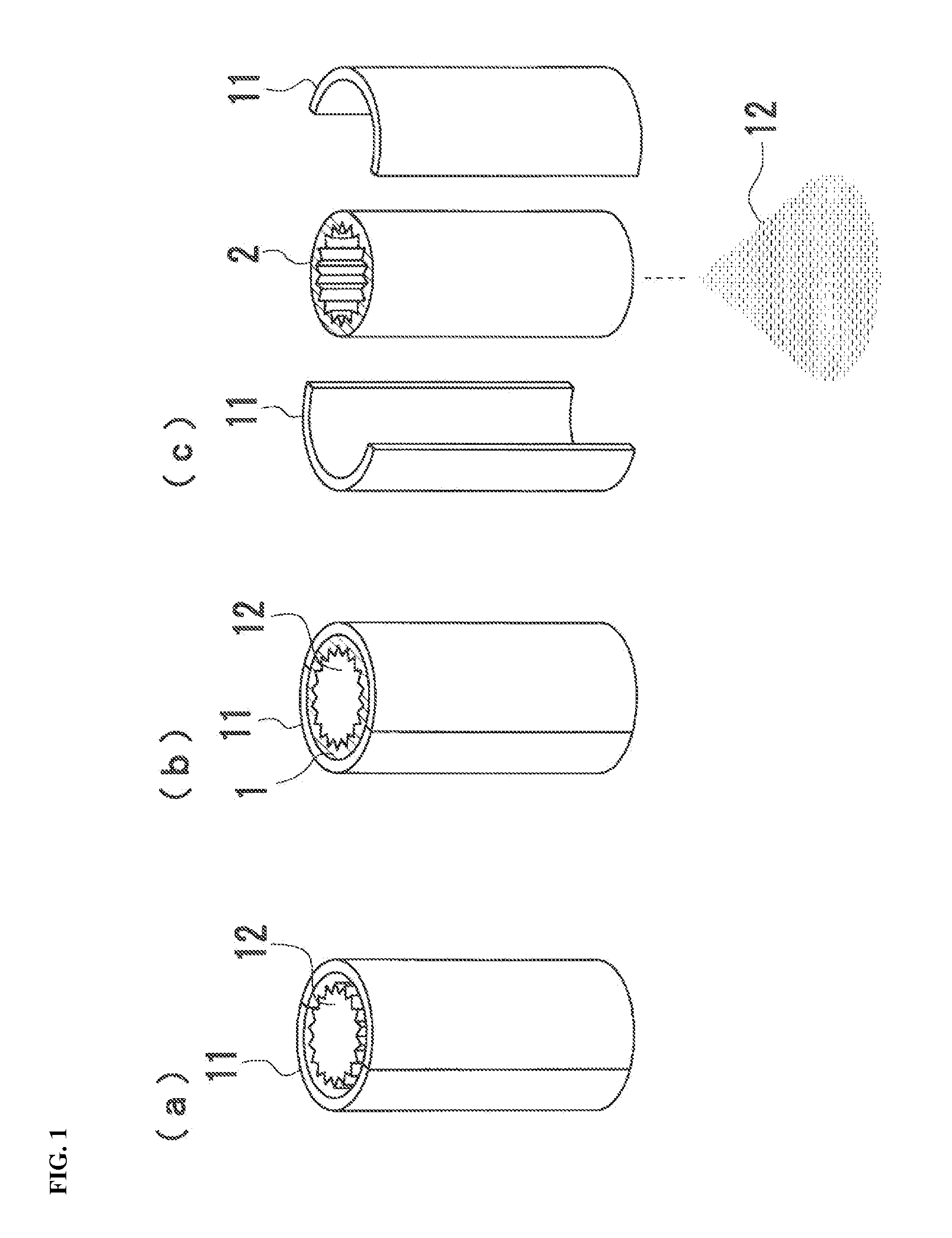
[0023]As shown in FIG. 1, a mold 11 and a core 12 are used in the embodiment of the internal gear manufacturing method according to the present invention.

[0024]The mold 11 is made of a metal excellent in thermal conductivity and has a long tubular shape. The mold 11 is dividable along a central axis thereof into two halves. In an illustrative example, the mold 11 has an outer diameter of 2 mm. If 100 mm long, the mold 11 will enable manufacturing of twenty internal gears at a time.

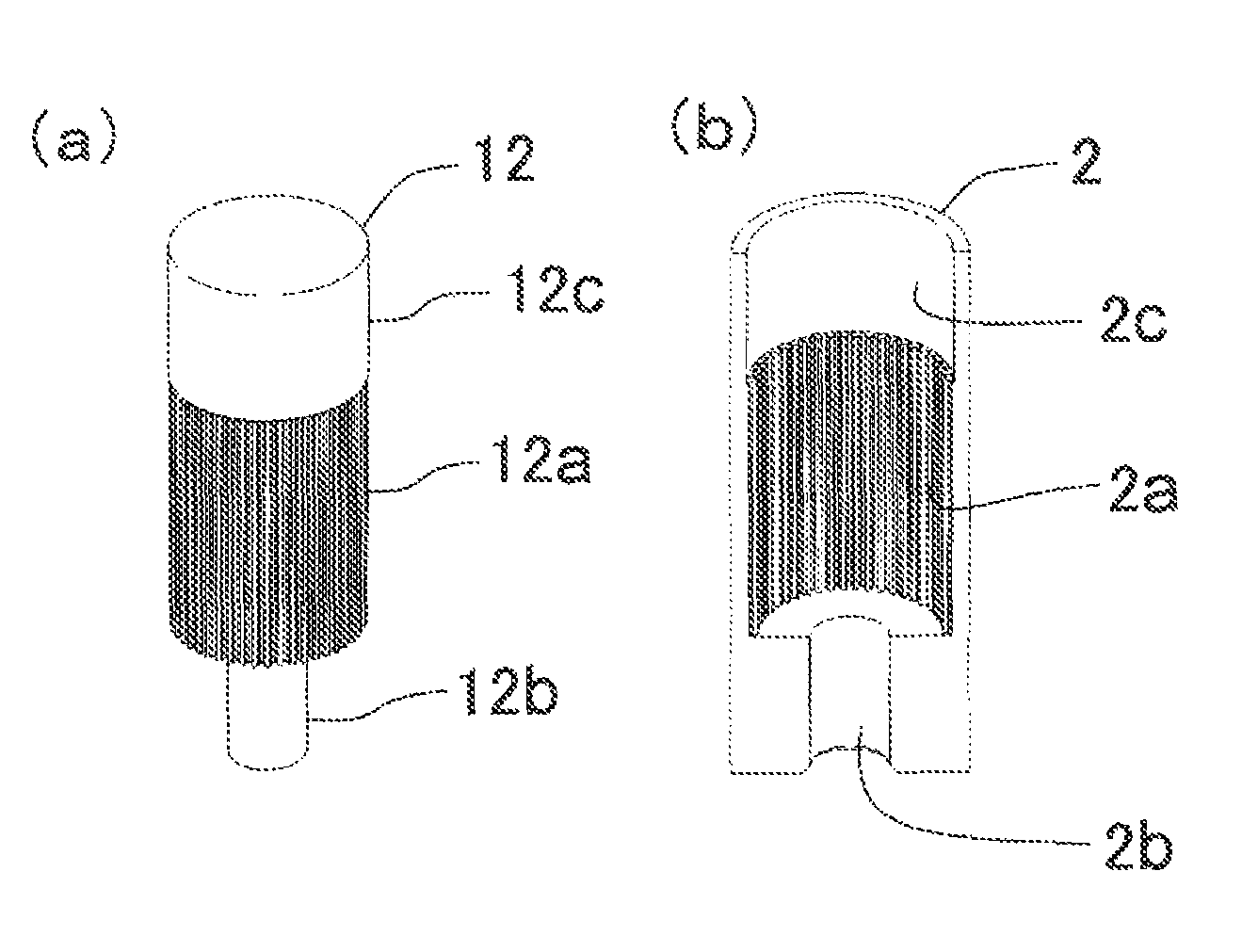
[0025]The core 12 is made of carbon with a melting point of 1,000° C. or higher and is formed into a shape of a thin, long external gear. The core 12 has a length equal to that of the mold 11 and an outer...


PUM

PropertyMeasurementUnit
melting pointaaaaaaaaaa
temperatureaaaaaaaaaa
outer diameteraaaaaaaaaa

Abstract

An internal gear manufacturing method capable of manufacturing time reduction and easy core removal, and a metallic glass internal gear manufactured thereby. A carbon core formed into a shape of an external gear is arranged in a thin, long tubular mold of a length equal thereto with a space extending longitudinally therealong. A molten metal material is pressure-injected under a temperature higher than a melting point thereof into the space between the mold and the core. The molten metal material is resolidified by rapid cooling at or above a critical cooling rate thereof together with the mold and the core. After resolidification of the molten metal material, the core is removed by pulverization or dissolution. Along internal gear formed of the resolidified metal material is cut into a plurality of segments of a prescribed length.

Description

FIELD OF THE INVENTION[0001]The present invention relates to an internal gear manufacturing method and a metallic glass internal gear manufactured thereby.BACKGROUND[0002]Included among the conventional internal gear manufacturing methods are those for cold-plastically forming gear teeth on an inner circumferential surface of a member press-formed into a cup shape by means of an internal gear forming die (for example, refer to Japanese Unexamined Patent Application Publication No. 1996-300083) and those for cutting gear teeth along an inner surface of a hollow member by press-inserting thereinto an internal gear tooth cutting chisel (for example, refer to Japanese Unexamined Patent Application Publication No. 2003-89015). Unfortunately, these conventional methods are not problem-free regarding precision and miniaturization. For example, when required to manufacture a miniaturized internal gear for use in precision devices, such as micro-geared motors that require high accuracy, the ...

Claims


Application Information

Patent Timeline
Patent Type & Authority Patents(United States)
IPC IPC(8): B22D27/15B22D29/00
CPCB22D27/15B22D29/001F16H55/06Y10T29/49467Y10T29/49474Y10T29/49989Y10T74/19Y10T29/49988Y10T29/4998Y10T29/49462
Inventor WANG, XINMININOUE, AKIHISASHIMIZU, YUKIHARU
Owner NAMIKI PRECISION JEWEL CO LTD
Why Eureka
Try Eureka