Exhaust gas treatment device for construction machine
a technology for exhaust gas treatment and construction machines, which is applied in the direction of machines/engines, transportation and packaging, and jet propulsion mounting, etc., can solve the problems of damage to the exhaust gas treatment device, the exhaust gas treatment member and the lik
- Summary
- Abstract
- Description
- Claims
- Application Information
AI Technical Summary
Benefits of technology
Problems solved by technology
Method used
Image
Examples
first embodiment
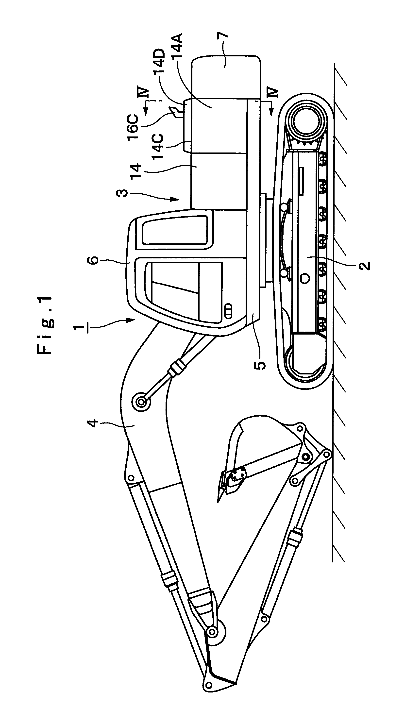
[0078]FIGS. 1 to 9 show the present invention. In FIG. 1, designated at 1 is a crawler type hydraulic excavator which is a typical example of construction machines, and this hydraulic excavator 1 is largely constituted by an automotive lower traveling structure 2, an upper revolving structure 3 which is swingably mounted on the lower traveling structure 2 and constitutes a vehicle body together with the lower traveling structure 2, and a working mechanism 4 liftably mounted on the front side of the upper revolving structure 3 to perform such as the operation of excavating earth and sand. The lower traveling structure 2 and the upper revolving structure 3 are specific examples of the vehicle body in accordance with the present invention.
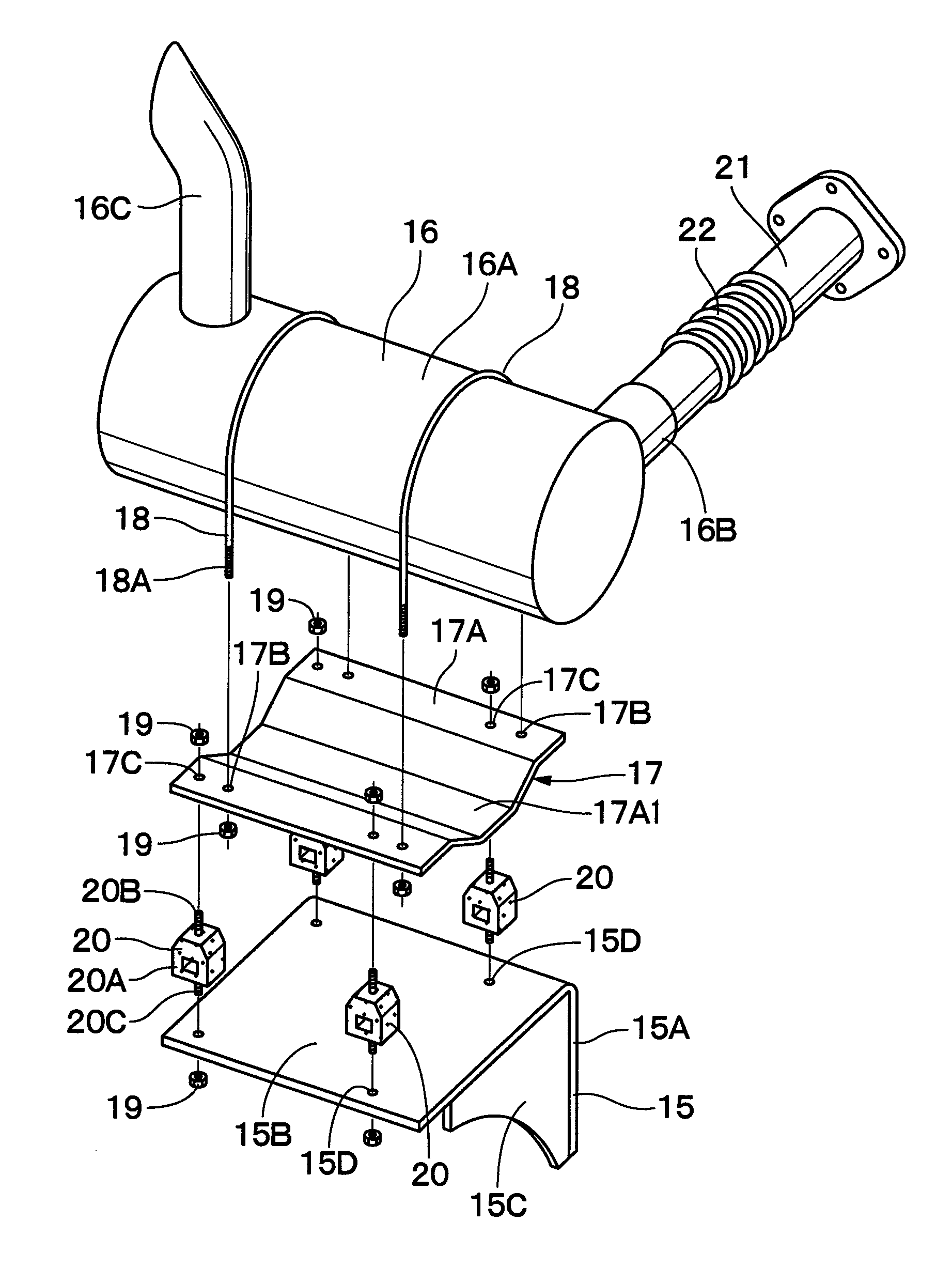
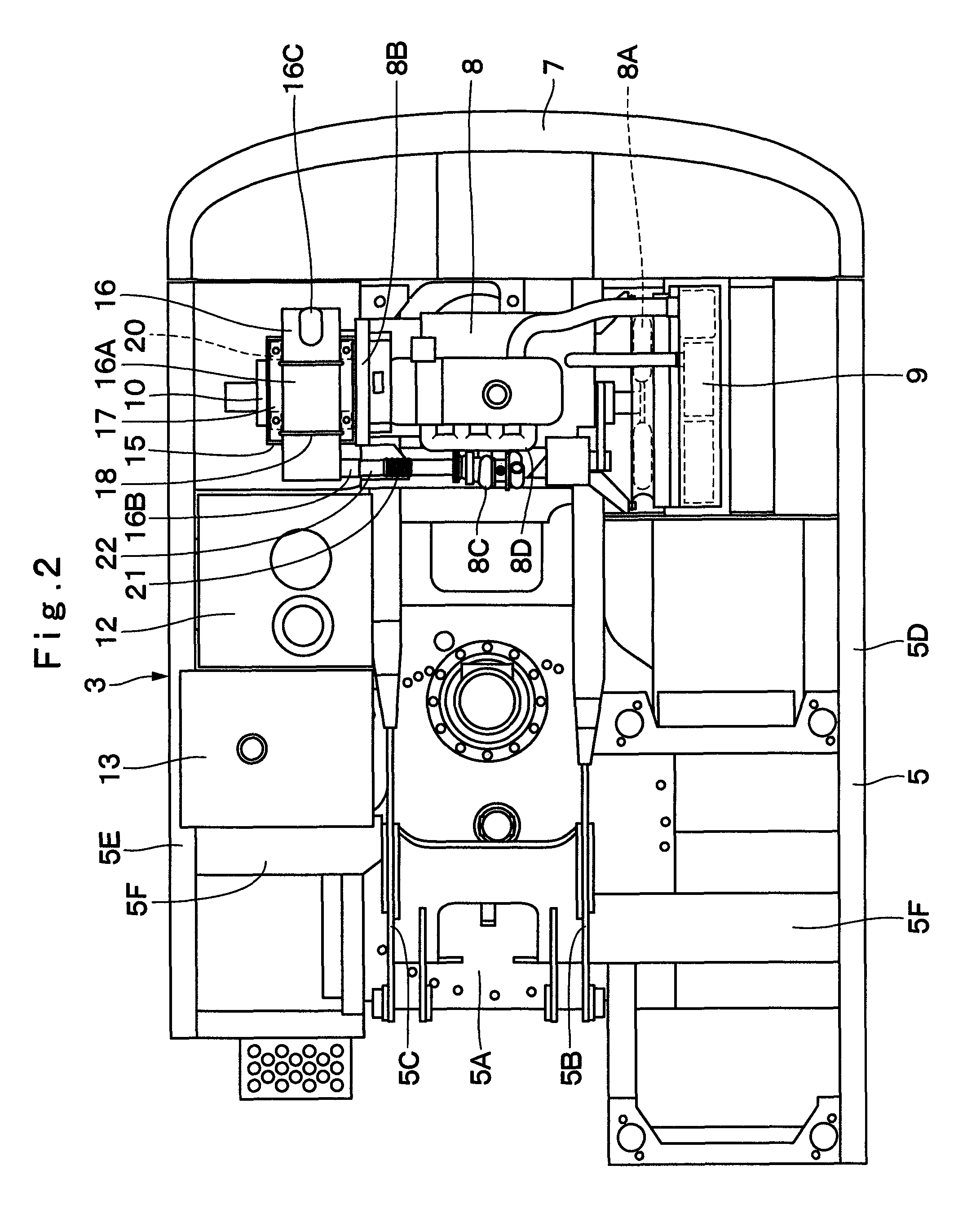
[0079]Here, the upper revolving structure 3 for constituting the hydraulic excavator 1 will be described in greater details. Indicated at 5 is a revolving frame of the upper revolving structure 3, and the revolving frame 5 is formed as a supporting st...
second embodiment
[0116]In FIG. 10, designated at 31 is a heat shielding cover in accordance with the second embodiment which is provided in such a manner as to cover the vibration isolating member 20. This heat shielding cover 31 is formed in the shape of a lidded cylinder by a cylinder portion 31A covering the periphery of the elastic deformation portion 20A of the vibration isolating member 20 and a lid portion 31B covering the upper side of the elastic deformation portion 20A. A passage hole 31C, into which the upper mounting screw portion 20B of the vibration isolating member 20 is inserted, is bored in the center of the lid portion 31B.
[0117]As a result, as the heat shielding cover 31 is fitted over the vibration isolating member 20 from above while the upper mounting screw portion 20B is inserted into the passage hole 31C, the heat shielding cover 31 is able to cover the elastic deformation portion 20A formed of a rubber material or the like. As a result, the heat shielding cover 31 is able to...
third embodiment
[0127]In FIGS. 11 and 12, designated at 41 is an exhaust gas treatment device in accordance with the third embodiment which is provided on the support member 15. This exhaust gas treatment device 41 is mounted on the supporting face portion 15B of the support member 15 by means of below-described mounting brackets 51 and 52 and the vibration isolating members 20. The exhaust gas treatment device 41 is largely constituted by an upstream cylinder 42, a downstream cylinder 43, an intermediate cylinder 44, an oxidation catalyst 46, and a particulate matter removing filter 47, and the like, which will be described hereinunder.
[0128]Namely, the exhaust gas treatment device 41 in accordance with the third embodiment is so constructed that three cylinders, namely, the upstream cylinder 42 located on the front side, the downstream cylinder 43 located on the rear side, and the intermediate cylinder 44 located therebetween, are flange-connected by use of bolts 45.
[0129]The upstream cylinder 42...
PUM
 Abstract
Description
Claims
Application Information
 - R&D
- Intellectual Property
- Life Sciences
- Materials
- Tech Scout
- Unparalleled Data Quality
- Higher Quality Content
- 60% Fewer Hallucinations
Browse by: Latest US Patents, China's latest patents, Technical Efficacy Thesaurus, Application Domain, Technology Topic, Popular Technical Reports.
© 2025 PatSnap. All rights reserved.Legal|Privacy policy|Modern Slavery Act Transparency Statement|Sitemap|About US| Contact US: help@patsnap.com


