Magnetically actuated mechanical diode

a mechanical diode and magnet technology, applied in the field of one-way clutches, can solve the problem that the clutch does not provide control over the operation of the clutch, and achieve the effect of preventing the free rotation of the clutch in one direction

Active Publication Date: 2013-04-16
FORD GLOBAL TECH LLC
View PDF24 Cites 64 Cited by
  • Summary
  • Abstract
  • Description
  • Claims
  • Application Information

AI Technical Summary

Benefits of technology

[0009]The electromagnetic coil is located in a pocket plate that contains pockets containing struts and return springs which provide the one-way clutch function. When the electromagnetic coil is energized, the struts are pulled away from the cams by magnetism, thus allowing free rotation of the clutch in either direction. In an alternative embodiment, the electromagnetic coil is mounted such that, when the electromagnet is energized, free rotation of the clutch in one direction is prevented.

Problems solved by technology

Such clutches provide no control over their operation, i.e., whether they lockup or rotate in the lockup direction.

Method used


Image

  • Magnetically actuated mechanical diode
  • Magnetically actuated mechanical diode
  • Magnetically actuated mechanical diode

Examples


Embodiment Construction

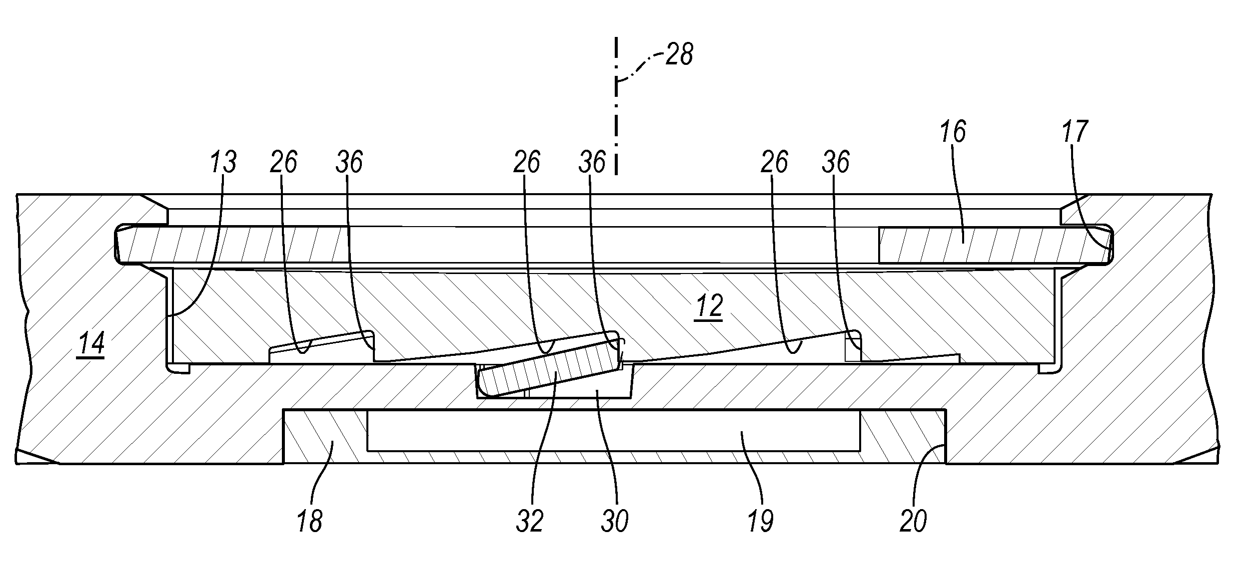
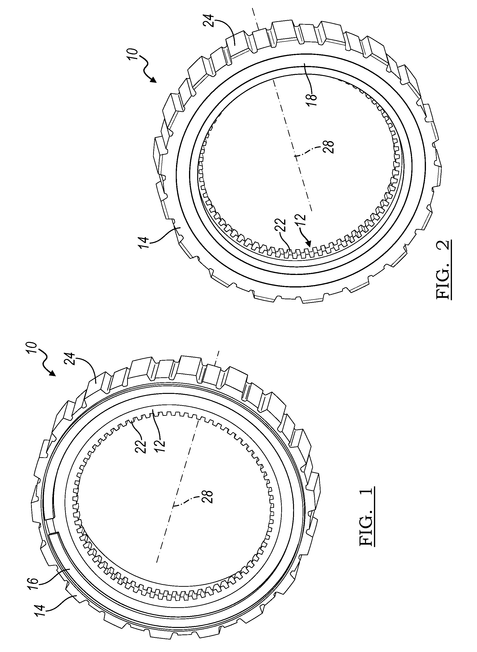
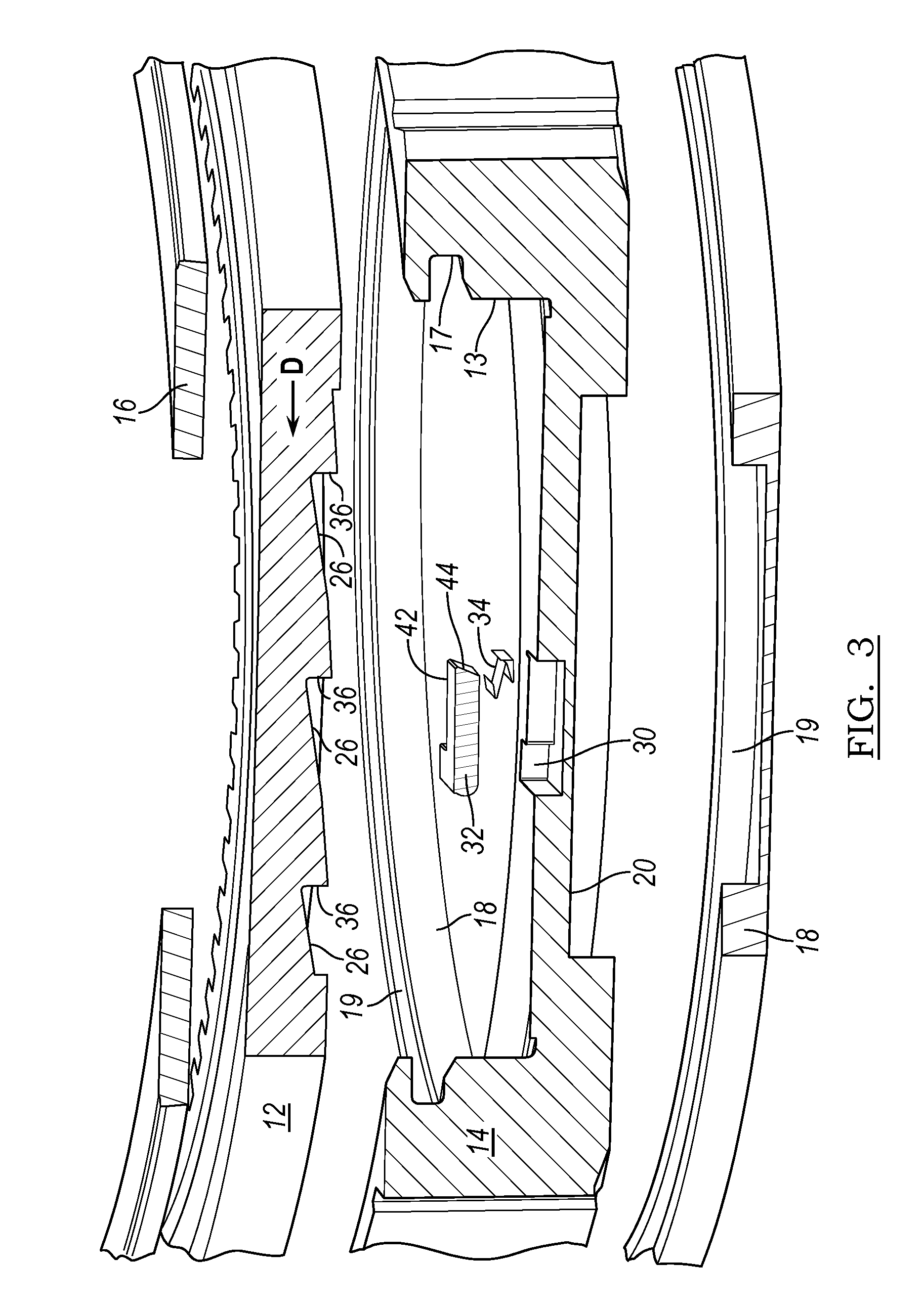
[0028]Referring now to FIGS. 1-4, a magnetic diode assembly 10, i.e., a magnetically actuated one-way clutch, includes a cam plate 12 concentric about an axis; a pocket plate 14, encircling the cam plate and including a recess 13; a snap ring 16 fitted into a groove 17 in plate 14 for securing the two plates together; and a bobbin 18 containing an coil of electrically conductive wire 19 fitted in a groove 20 formed in rear surface of the pocket plate. The radial inner surface of cam plate 12 is formed with axially directed spline teeth 22, and the radial outer surface of pocket plate 14 is formed with axially directed spline teeth 24.

[0029]Cam plate 12 is formed with a series of cams 26 spaced about a central longitudinal axis 28, which is concentric with recess 13.

[0030]Pocket plate 14 is formed with a series of pockets 30, spaced about axis 28, each pocket containing a strut 32 and a spring 34, which continually urges the respective strut to pivot along axis 28 into contact with t...


PUM


Abstract

A one-way clutch includes a first plate including cams distributed about an axis, a second plate axially facing the cams and including pockets, a coil located in one of the plates, struts, each strut supported in one of the pockets for pivoting axially relative to the cams in response to an electromagnetic field induced by current in the coil, and springs urging the struts to pivot opposite a pivot direction caused by energizing the coil.

Description

BACKGROUND OF THE INVENTION[0001]1. Field of the Invention[0002]This invention relates generally to a one-way clutch, particularly to a one-way clutch, whose states of engagement and disengagement are controlled electromagnetically by axially pivoting a locking element.[0003]2. Description of the Prior Art[0004]A conventional one-way clutch (OWC) overruns when one of its races rotates in one direction relative to the other race, and it engages or locks in the other direction. Such clutches provide no control over their operation, i.e., whether they lockup or rotate in the lockup direction.[0005]There are, however, functional requirements wherein a one-way clutch could provide a new, wider range of functions if control were provided. For example, it is desirable to have a OWC overrun in either rotary direction until a command causes the clutch to lockup. In another instance, it is desirable for a OWC that conventionally overruns in one direction and locks in the other to lockup in bo...

Claims


Application Information

Patent Timeline
Patent Type & Authority Patents(United States)
IPC IPC(8): F16D41/12F16D27/02
CPCF16D41/125F16D41/14F16D27/02F16D41/16
Inventor BIRD, NORMAN J.
Owner FORD GLOBAL TECH LLC
Why Eureka
Try Eureka