Cutting insert, cutting tool using the same, and cutting method

a cutting tool and insert technology, applied in the direction of metal-working equipment, metal-working apparatus, milling equipment, etc., can solve the problems of low cutting performance and large cutting force, and achieve the effect of excellent cutting performance and small cutting for

Active Publication Date: 2013-04-16
KYOCERA CORP
View PDF22 Cites 10 Cited by
  • Summary
  • Abstract
  • Description
  • Claims
  • Application Information

AI Technical Summary

Benefits of technology

[0007]An advantage of the invention is to provide a cutting insert and a cutting tool using the cutting insert as well as a cutting method, which are subjected to small cutting force and have excellent cutting performance.
[0008]In order to solve the above problem, the present inventor carried out intensive research to find the solution composed of the following configuration, thereby completing the present invention.
[0009]Specifically, a cutting insert of the invention comprise a cutting edge formed at a ridge between an upper surface and a side surface. The side surface has a plurality of grooves extending from the side surface to the upper surface to divide the cutting edge. Clearance angles within the grooves increase from one end of the cutting edge toward the other end of the cutting edge.
[0010]Other cutting insert of the invention comprises an insert main body having an upper surface and a plurality of side surfaces, a cutting edge located between both ends of a ridge which is between at least one side surface among the side surfaces and the upper surface, a high-positioned portion located at one end of the ridge, and a low-positioned portion located lower in a thickness direction of the insert main body than the high-positioned portion and located at the other end of the ridge. A plurality of grooves extends from the side surface to the upper surface to divide the cutting edge by the grooves. In the plurality of grooves, the clearance angle within the groove nearest to the low-positioned portion is greater than the clearance angle within the groove nearest to the high-positioned portion.
[0011]A still other cutting insert of the invention comprises an insert main body having an upper surface and a plurality of side surfaces, a cutting edge located between both ends of a ridge which is between at least one side surface among the side surfaces and the upper surface, a high-positioned portion located at one end of the ridge, and a low-positioned portion located lower in a thickness direction of the insert main body than the high-positioned portion and located at the other end of the ridge. The cutting edge comprises a first flat cutting edge having substantially the same height as the high-positioned portion, a second flat cutting edge having substantially the same height as the low-positioned portion, and a tilted cutting edge having a height decreasing from the high-positioned portion toward the low-positioned portion and located between the first flat cutting edge and the second flat cutting edge. A plurality of grooves extends from the side surface to the upper surface to divide the cutting edge by the grooves. The side surface comprises a first flank connecting to the first flat cutting edge, a second flank connecting to the tilted cutting edge, and a third flank connecting to the second flat cutting edge. “a”, “b” and “c” satisfy the relationship of a<b<c, wherein “a” represents the clearance angle within the groove formed at the first flank, “b” represents the clearance angle within the groove formed at the second flank, and “c” represents the clearance angle within the groove formed at the third flank.Effect of the Invention
[0012]According to the embodiment of the present invention, the plurality of grooves extends from the side surface to the upper surface to divide the cutting edge. Therefore, when cutting is carried out by using the cutting insert comprising these grooves, the portions of a work material corresponding to the grooves are not cut, and cutting force can be decreased by the amount of the uncut portions.

Problems solved by technology

However, there is the problem that the cutting insert 101 thus constructed is subjected to large cutting force during cutting, and has low cutting performance.

Method used


Image

  • Cutting insert, cutting tool using the same, and cutting method
  • Cutting insert, cutting tool using the same, and cutting method
  • Cutting insert, cutting tool using the same, and cutting method

Examples


Embodiment Construction

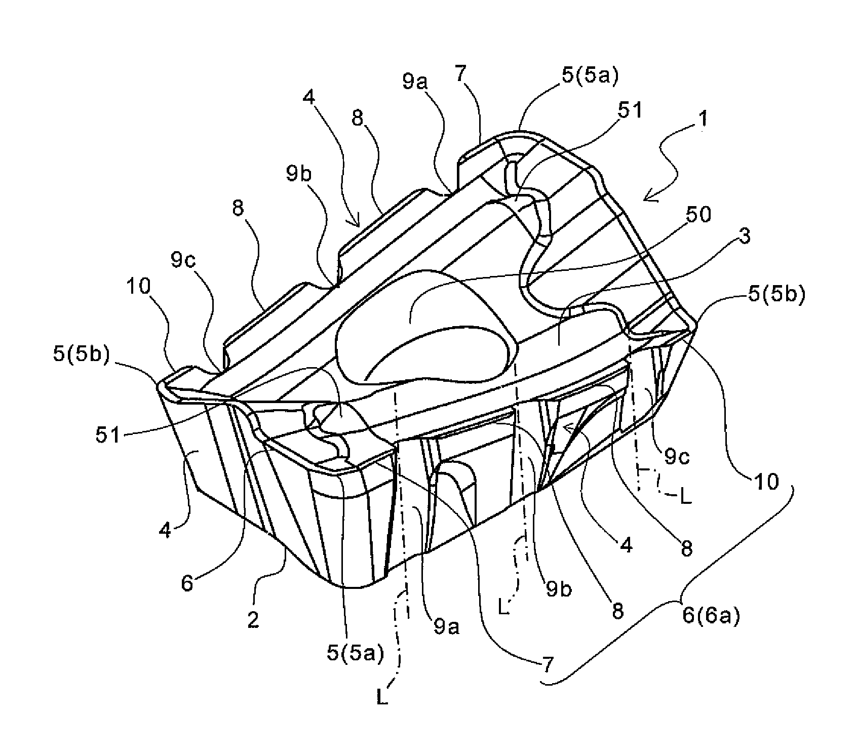
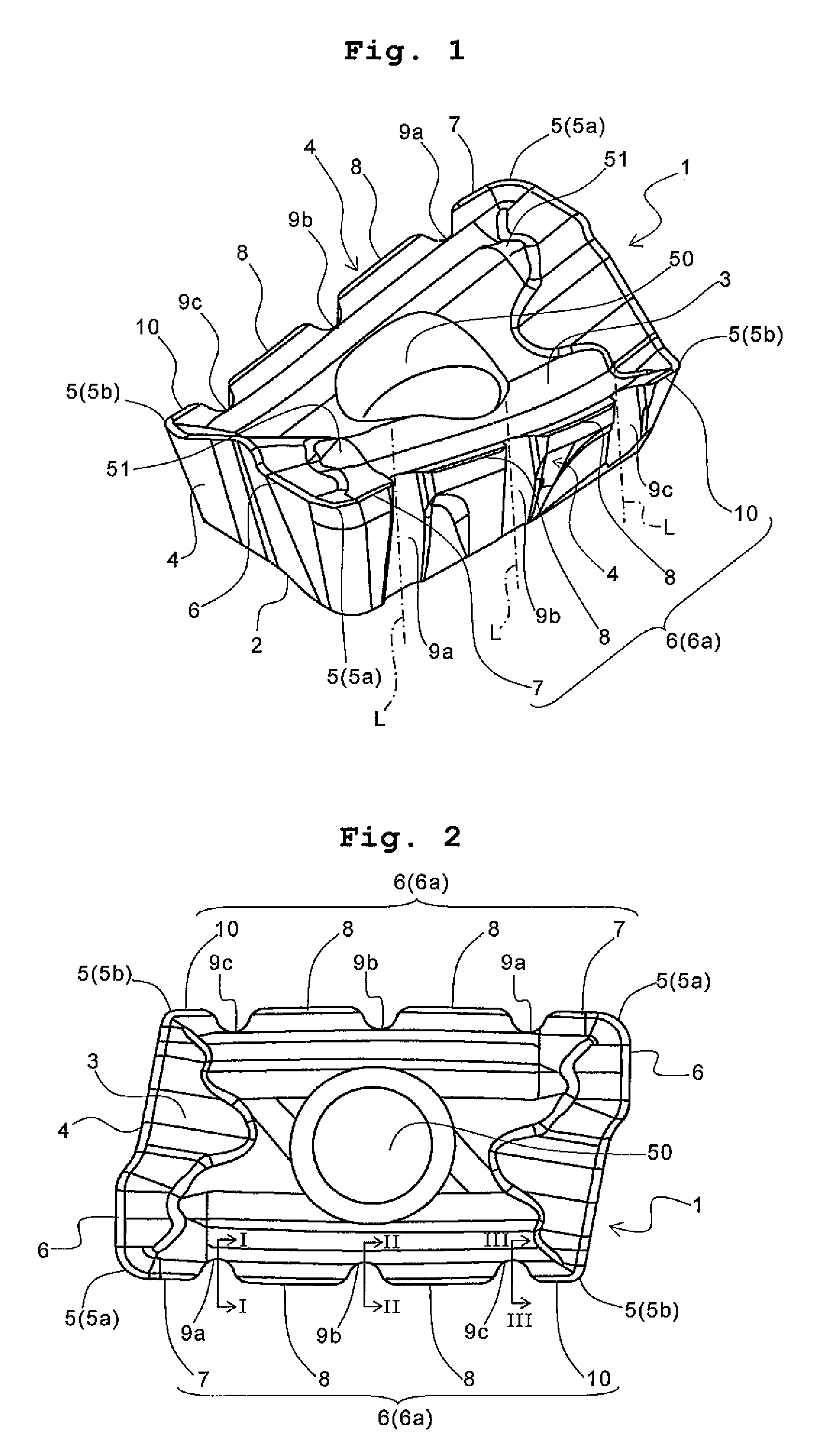
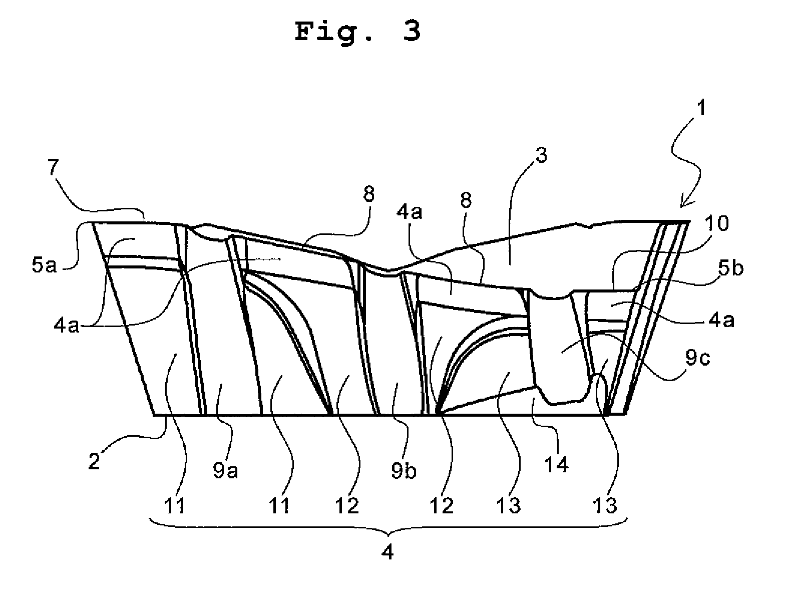
[0033]A preferred embodiment of the cutting insert according to the invention is described in detail with reference to the accompanying drawings.

[0034]As shown in FIGS. 1 to 3, the cutting insert according to the preferred embodiment (hereinafter referred to simply as an insert) 1 comprises an insert main body having substantially a parallelogram when viewed from above. The insert 1 comprises a bottom surface 2 serving as a seat surface, an upper surface 3 having a rake face, and a side surface 4 having a flank. The insert 1 comprises further corner portions 5 (5a and 5b) located at the corner parts of the insert main body in a ridge between the upper surface 3 and the side surface 4, and a cutting edge 6 located between these two corner portions 5 and 5 in the ridge (namely between both ends of the ridge) and connected to these two corner portions 5 and 5.

[0035]The rake face of the upper surface 3 means the face of the upper surface 3, through which generated chips graze. A through...


PUM

PropertyMeasurementUnit
clearance angleaaaaaaaaaa
thicknessaaaaaaaaaa
heightaaaaaaaaaa

Abstract

A cutting edge is formed at a ridge between an upper surface and a side surface. In the side surface, a plurality of grooves are formed so as to extend from the side surface to the upper surface to divide the cutting edge, and the clearance angles within these grooves are formed so as to increase from one end of the cutting edge toward the other end of the cutting edge. This achieves a cutting insert having small cutting force and excellent cutting performance. Among the plurality of grooves, the groove nearest to the one end of the cutting edge has preferably a width increasing from the upper surface of the cutting insert toward the lower surface.

Description

CROSS-REFERENCE TO THE RELATED APPLICATIONS[0001]This application is a national stage of international application No. PCT / JP2007 / 069108 filed Sep. 28, 2007, which also claims the benefit of priority under 35 USC 119 to Japanese Patent Application No. 2006-268837 filed Sep. 29, 2006, the entire contents of which are incorporated herein by reference.TECHNICAL FIELD[0002]The present invention relates to a cutting insert mounted on a cutting tool used for cutting of materials such as metal materials, and a cutting tool using the cutting insert, as well as a cutting method.BACKGROUND ART[0003]Examples of the cutting tool generally used for cutting metal materials and the like include those that a cutting insert having a cutting edge is mounted thereon. For example, Patent Document 1 describes a predetermined cutting insert, and a cutting tool with the cutting insert mounted thereon (specifically, an end mill).[0004]FIG. 12(a) is a side view showing the related art cutting tool as descri...

Claims


Application Information

Patent Timeline
Patent Type & Authority Patents(United States)
IPC IPC(8): B23C5/02B23C5/16B23C5/26
CPCB23C5/109B23C5/207B23C2200/085B23C2200/128B23C2200/205Y10T407/1924Y10T407/23Y10T407/1942Y10T407/235Y10T407/2268Y10T407/22B23C2220/48B23C5/202
Inventor HATTA, KAORU
Owner KYOCERA CORP
Why Eureka
Try Eureka