Generator arrangement for a wind power plant

a generator arrangement and wind power technology, applied in the direction of electric generator control, magnetic circuit shape/form/construction, magnetic circuit rotating parts, etc., can solve the problems of generator material consumption, low rigidity, and insufficient rigidity of the support structure, and achieve the effect of low weight and high rigidity

Inactive Publication Date: 2013-04-16
SCHULER PRESSEN GMBH & CO KG
View PDF6 Cites 2 Cited by
  • Summary
  • Abstract
  • Description
  • Claims
  • Application Information

AI Technical Summary

Benefits of technology

[0007]With the generator arrangement according to the invention at least one main bearing is arranged between the generator and the hub wherein the rotor of the generator is supported only on the front end of a rigid carrier in the form of a support disc 30. The support disc 30 is a hollow chamber structure of low weight and high rigidity.
[0009]This set-up permits the arrangement of the bearings between the generator and the hub and the very sturdy structure for the support tube as well as the support disc provided for establishing a connection between the support and the rotor. The double wall support structure of the support disc together with a preferably also double-walled support structure of the stator provides for a good, distortion-free accommodation of the effective forces. With the arrangement of the main bearing outside of the generator, the arrangement consisting of the support tube and the support structure of the stator can be optimized with respect to its rigidity while a clear structure and a low over-all weight are obtained. The double-wall support structure with radial webs or, respectively, ribs for the rotor and the stator of the generator make it possible to achieve a high rigidity at a relatively low weight. This has a positive effect on the resonance frequency of the arrangement and consequently the oscillation or vibration behavior of the generator. The generator and the whole wind power plant can be made more cost effective and weight-optimized.
[0010]The arrangement of the main bearings between the generator and the hub minimizes bearing load.
[0011]With the concept disclosed herein a support tube of a particularly large diameter can be used. This results in a rigid structure of low weight. The radial height of the support structure of the generator, in particular the support disc of the rotor and the support structure of the stator can be kept small which clearly enhances the rigidity.
[0013]Independently of whether a moment bearing or two axially spaced bearing are used, the gondola, that is, the machine carrier, is free of elements of the generator and the main bearing. It can therefore be designed for optimum strength and rigidity. Access to the tower is not inhibited.
[0014]Preferably the rotor extends in a cantilevered fashion away from the support disc. It is therefore supported only at one end thereof. With the high rigidity of the support disc in the form of a hollow structure the precise maintenance of operating air clearances in the generator is possible with the required accuracy. The rigidity of the support disc supports its capability of the sleeve-like rotor to remain undistorted so that the desired air gaps are maintained.

Problems solved by technology

The arrangement of the main bearing within the directly driven generator can result in problems regarding the establishment of a sufficiently rigid support structure.
At the same time, however, the weight of the generator is an important expense factor.
It results not only in generator material consumption, that is costs, but also affects directly the expenditures involved in the design and constrictions of the gondola, the tower and the foundation of the wind power plant.
In addition, there are respective transport costs and mounting expenditures.

Method used


Image

  • Generator arrangement for a wind power plant
  • Generator arrangement for a wind power plant
  • Generator arrangement for a wind power plant

Examples


Embodiment Construction

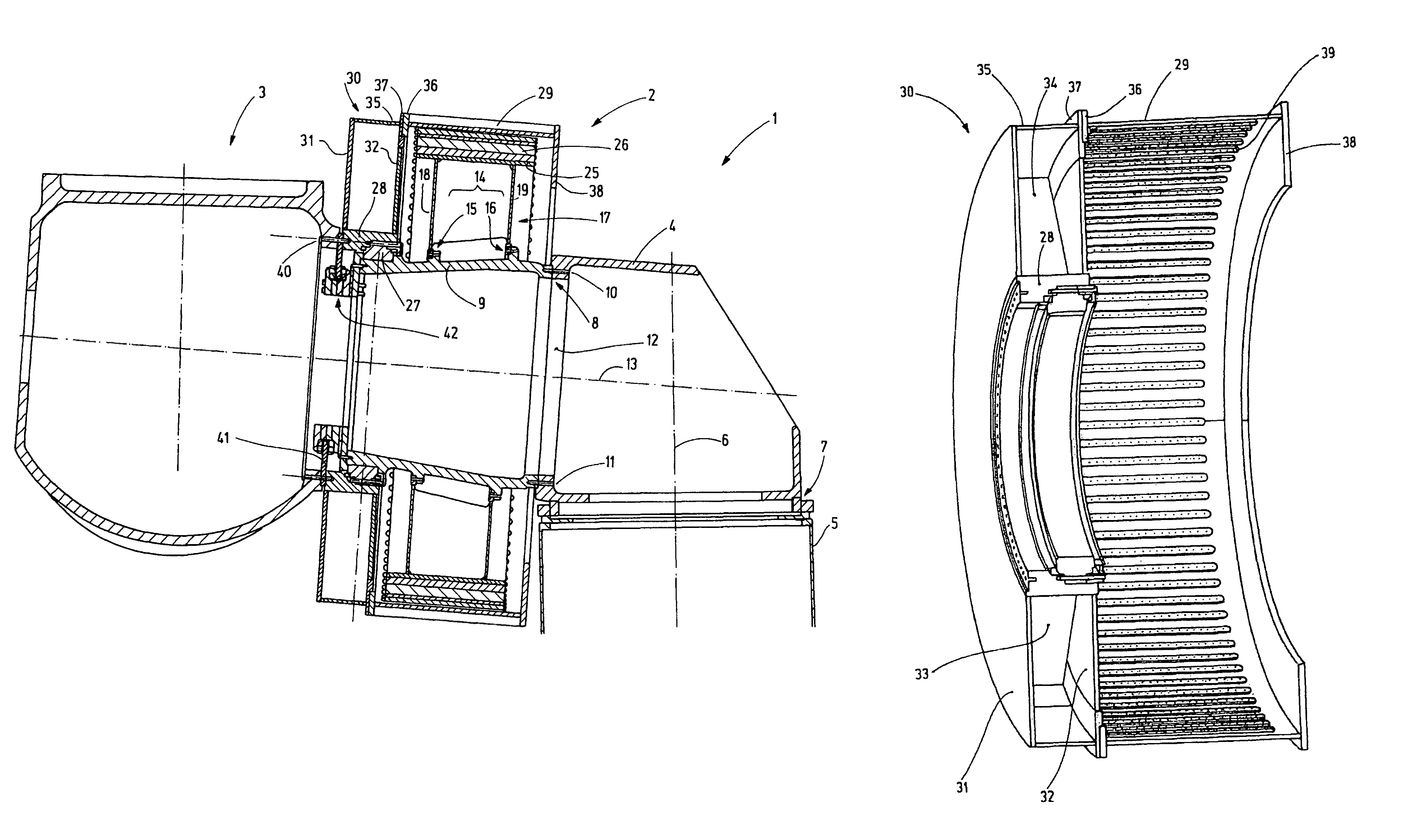
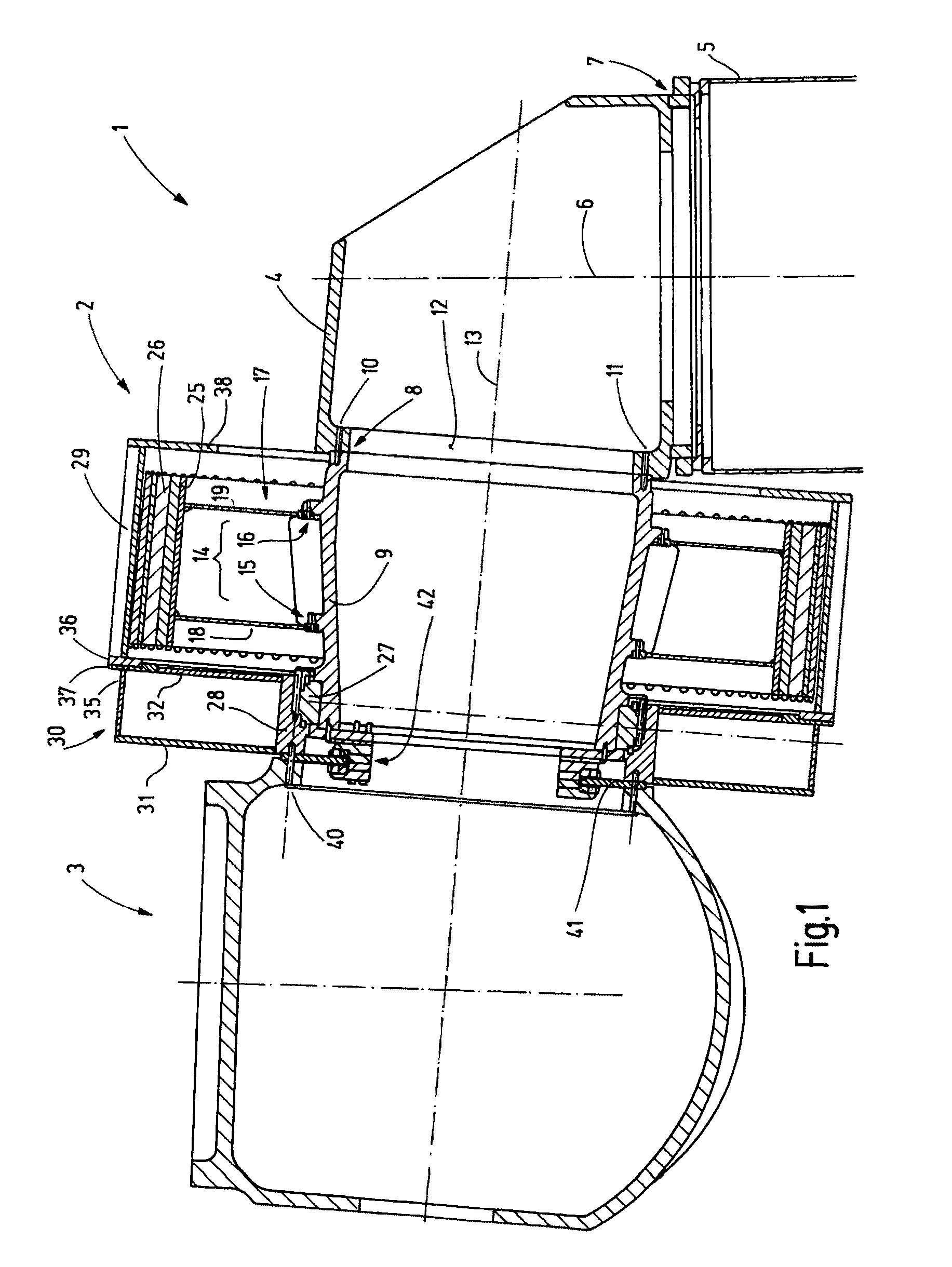
[0023]FIG. 1 shows a tower head 1 with a generator 2 and a hub 3 of a wind power plant. The tower head includes a machine carrier 4 which is supported at the upper end 5 of the tower so as to be rotatable about a vertical axis 6. To this end the tower is provided with a tower bearing 7.

[0024]In the shown embodiment the machine carrier 4 is relatively compact. It extends sidewardly only slightly beyond the upper end 5 of the tower. At one side, in FIG. 1 at the left, the machine carrier 4 is provided with a support structure 8 for supporting a support tube 9 forming a stationary axle. The support tube 9 is provided at its side adjacent the machine carrier 4 with a precisely machined annular surface which forms a sealing surface to which a corresponding annular surface formed on the machine carrier 4 is assigned. The annular surface of the machine carrier 4 may be surrounded by an annular stepped area so that the support tube is seated on the machine carrier 4 in a centered manner. As...


PUM


Abstract

In the generator arrangement according to the invention at least one main bearing is arranged between the generator and the hub wherein the rotor of the generator is supported only on the front end of a rigid carrier in the form of a support disc (30). The support disc is a hollow chamber structure of low weight and high rigidity.

Description

CROSS-REFERENCE TO RELATED APPLICATION[0001]This application claims the priority benefits of German Application No. 10 2009 017 865.1 filed Apr. 17, 2009.BACKGROUND OF THE INVENTION[0002]The invention resides in a generator arrangement for wind energy utilization. Plants for wind energy utilization generally comprise a vertical extending tower on the top of which a gondola is supported so as to be rotatable about a vertical axis. The gondola supports a generator which is usually driven by a three-blade rotor. One of the employed drive concepts is a direct drive wherein the hub of the rotor carrying the blades is connected to the rotor of a generator directly without an intermediate transmission.[0003]Such a concept is shown in DE 44 02 184 C2, wherein the generator is in the form of an external rotor. The stator and the rotor of the generator are joined by a resilient bearing structure which is arranged within the generator and which supports the rotational movement of the rotor as ...

Claims


Application Information

Patent Timeline
Patent Type & Authority Patents(United States)
IPC IPC(8): F03D9/00
CPCF03D11/0008H02K1/187H02K1/30H02K7/183H02K1/2786Y02E10/72H02K7/1838F03D80/70H02K1/2791
Inventor LAUKE, ANDREAS
Owner SCHULER PRESSEN GMBH & CO KG
Why Eureka
Try Eureka