Power supply device

a power supply device and torque technology, applied in the direction of power conversion systems, dynamo-electric converter control, electric generator control, etc., can solve the problems of increasing the size and cost of the power supply device, and achieve the effect of reducing the operating load of the torque supply device, suppressing the energy needed, and improving power generation efficiency

Active Publication Date: 2013-04-16
MITSUBISHI ELECTRIC CORP
View PDF15 Cites 4 Cited by
  • Summary
  • Abstract
  • Description
  • Claims
  • Application Information

AI Technical Summary

Benefits of technology

[0007]The present invention has been made to solve the problem described above, and therefore it is an object thereof to provide a power supply device using a magneto AC generator, which is capable of improving power generation efficiency compared with a conventional one by switching voltage control between opening control and short-circuit control of an output end of the magneto AC generator in accordance with an operating state of a rotor or a torque supplying device so that input torque to the magneto AC generator may be reduced to reduce an operating load on the torque supplying device and to suppress energy necessary for rotating the rotor for power generation.
[0009]According to the power supply device of the present invention, the opening control and the short-circuit control are switched over in accordance with the operating state of the rotor or the torque supplying device so that the input torque to the magneto generator may be reduced to reduce the operating load on the torque supplying device and to suppress energy necessary for rotating the rotor for power generation. Therefore, power generation efficiency may be improved compared with a conventional one.

Problems solved by technology

For this reason, the generator of the conventional power supply device does not necessarily generate power with input torque most suitable for an operating state of the rotor or the torque supplying device.
For this reason, an element with high withstand voltage must be selected, which leads to an increased size and cost of the power supply device.

Method used


Image

  • Power supply device
  • Power supply device
  • Power supply device

Examples


first embodiment

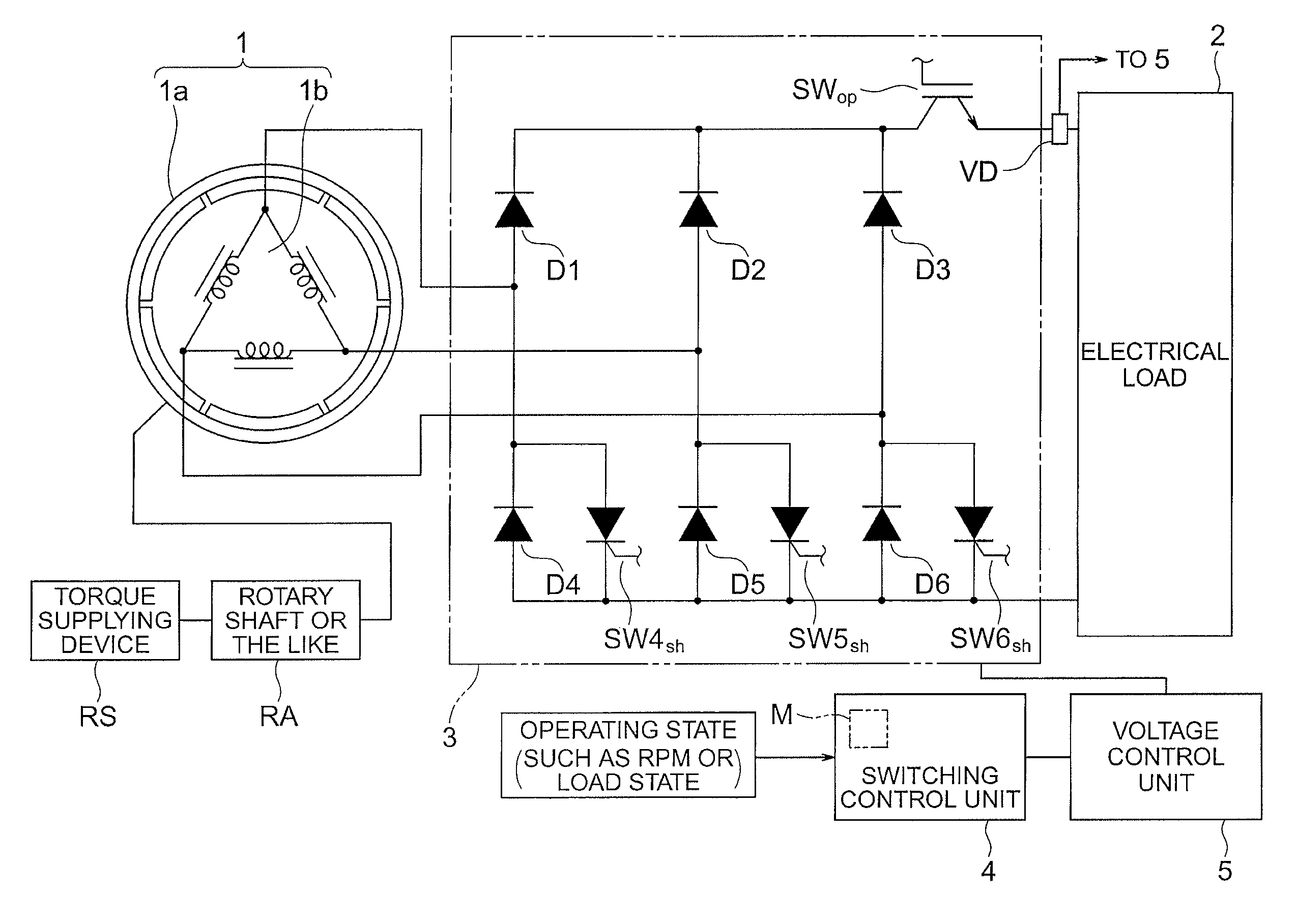
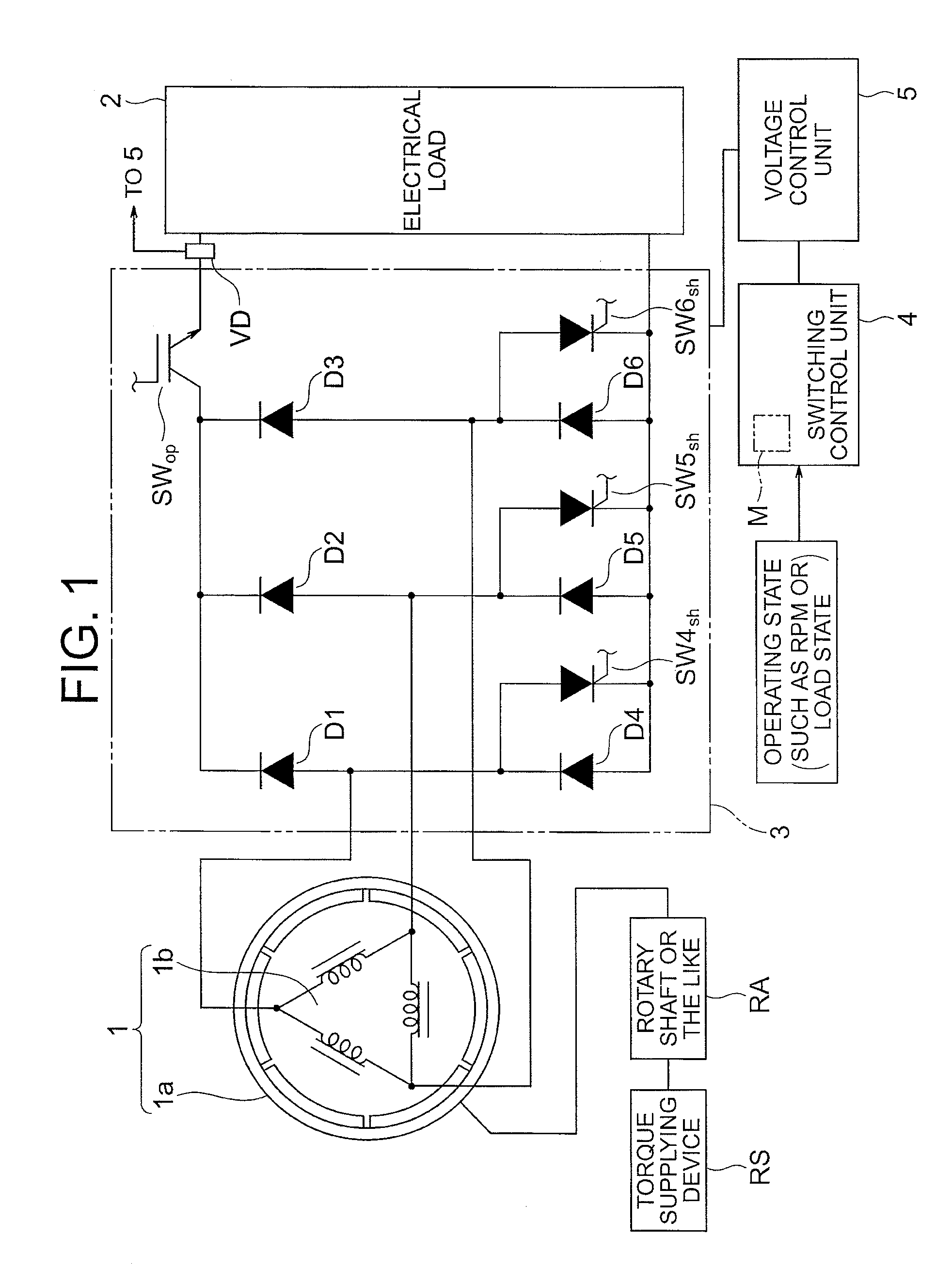
[0017]FIG. 1 is a diagram illustrating an overall structure of a power supply device according to a first embodiment of the present invention. The power supply device according to the first embodiment includes a magneto (AC) generator 1, a rectifying unit 3 which rectifies an alternating current generated by the magneto generator 1 to a direct current, an electrical load 2 to which electric power of the direct current rectified by the rectifying unit 3 is supplied, a voltage detection unit VD formed of a voltmeter for determining a voltage of the electrical load 2, opening means SWop, which is provided in the rectifying unit 3, for interrupting electrical conduction between an output end of the magneto generator 1 (in this embodiment, an output on a positive wave side of the rectifying unit 3) and the electrical load 2, short-circuiting means SW4sh to SW6sh, which are provided in the rectifying unit 3, for electrically short-circuiting the output end of the magneto generator 1, a vo...

second embodiment

[0030]An overall structure of a power supply device according to a second embodiment of the present invention is basically the same as that of the first embodiment illustrated in FIG. 1.

[0031]FIG. 4 illustrates characteristics of a generator output end voltage with respect to the rpm of the rotor 1a according to various methods of controlling the voltage of the electrical load 2. During the opening operation, a no-load induced voltage is generated at the output end of the magneto generator 1. As illustrated in FIG. 4, the no-load induced voltage is proportional to the rpm of the rotor 1a, and becomes the maximum at the actual maximum rpm. For this reason, in FIG. 4, in an area in which the generator output end voltage during the opening operation is less than a predetermined value Vup, the voltage of the electrical load 2 is controlled by the opening control. On the other hand, in an area in which the generator output end voltage is equal to or larger than the predetermined value Vu...

third embodiment

[0034]FIG. 5 is a diagram illustrating an overall structure of a power supply device according to a third embodiment of the present invention. In the power supply device according to this embodiment, as illustrated by a rectifying unit 3a of FIG. 5, thyristors SW1scr, SW2scr, and SW3scr, which have a rectifying function and also serve as opening means, are provided in place of the diodes D1 to D3 on the positive wave side of the three-phase diode bridge. In addition, transistors SW4mos, SW5mos, and SW6mos formed of MOSFETs, which have a rectifying function and also serve as short-circuiting means, are provided in place of the diodes D4 to D6 on the negative wave side. With the structure described above, the rectifying unit and the short-circuiting means may be formed integrally together. Note that an operation, a control, and the like of the power supply device are identical with those described above in each of the above-mentioned embodiments.

[0035]Note that, in each of the above-m...


PUM


Abstract

A power supply device comprising: a magneto generator including a rotor including a magnet forming a magnetic field; a rectifying unit rectifying an alternating current of the generator to a direct current and supplying to an electrical load; a voltage detection unit detecting a voltage of the electrical load; an opening unit interrupting electrical conduction of an output of the generator; short-circuiting units electrically short-circuiting the output; a torque supplying device supplying torque to the rotor; a voltage control unit selectively performing one of opening-control of controlling on / off switching of the opening unit and short-circuit-control of controlling on / off switching of the short-circuiting units to control the voltage of the electrical load to a predetermined value in accordance with the voltage detected by the voltage detection unit; a switching control unit switching and controlling between the above two controls in accordance with an operating state regarding rotation of the rotor.

Description

BACKGROUND OF THE INVENTION[0001]1. Field of the Invention[0002]The present invention relates to a power supply device using a magneto alternating current (AC) generator.[0003]2. Description of the Related Art[0004]As a power supply device, there is conventionally known, for example, a power supply device using a magneto AC generator disclosed in each of Japanese Patent No. 4100793, Japanese Utility Model Registration No. 2076397, and Japanese Utility Model Registration No. 2530219. Such power supply device generally includes a magneto AC generator, a rectifier circuit, and a generated voltage control circuit. Electric power generated by the magneto AC generator is converted into a direct current (DC) by the rectifier circuit, and then input to the generated voltage control circuit. The generated voltage control circuit performs short-circuit control or opening control so as to obtain a voltage in accordance with a voltage of an electrical load formed of, for example, an electrical ...

Claims


Application Information

Patent Timeline
Patent Type & Authority Patents(United States)
IPC IPC(8): H02P9/14
CPCH02P9/48H02M1/0085
Inventor ITOI, NAOKIMAEDA, MASAYOSHIKIHARA, NOBUHIROISHI, KENJIOKUDA, HIROSHIUEMURA, FUMITO
Owner MITSUBISHI ELECTRIC CORP
Why Eureka
Try Eureka