Check patentability & draft patents in minutes with Patsnap Eureka AI!

Active spot array lithographic projector system with regulated spots

a technology of lithographic projectors and spots, applied in the field of active spot array lithographic projector systems with regulated spots, can solve the problems of reduced aperture size, inadequate image light, and lessen the resolution of the resulting projected image,

Inactive Publication Date: 2013-04-16
CORNING INC
View PDF9 Cites 0 Cited by
  • Summary
  • Abstract
  • Description
  • Claims
  • Application Information

AI Technical Summary

Benefits of technology

The invention is an active spot array projection system that uses a spatial light modulator to create a light beam with individually addressable elements. These elements have irregular boundaries, which can affect the ultimate placement of the light beams. A focusing array focuses the light beams into spots. An imaging optic creates images of the addressed elements onto a focusing array. A spatial frequency filter is used to attenuate certain spatial frequencies of light arising from the irregularities of the elements, while maintaining high resolution and regulating the light distribution to reduce crosstalk between the spots. The effect of the spatial frequency filter is to restore radial symmetry among a distribution of angles that converge to form the spot.

Problems solved by technology

However, imperfections within the addressable elements can distort the size and shape of the spots, and thereby lessen resolution of the resulting projected image.
While it may be possible to stop down an aperture of an imaging lens within the projection system for removing the increased range of angular reflections of light from the micromirrors, the reduced aperture size also limits the capability of the projection system to distinguish between light segments emerging from adjacent micromirrors.
Instead of each microlens receiving light from just its associated micromirror, inadequately imaged light from individual micromirrors can spread into adjacent microlenses and partially illuminate focused spots not intended for generating the desired image.

Method used


Image

  • Active spot array lithographic projector system with regulated spots
  • Active spot array lithographic projector system with regulated spots
  • Active spot array lithographic projector system with regulated spots

Examples


Embodiment Construction

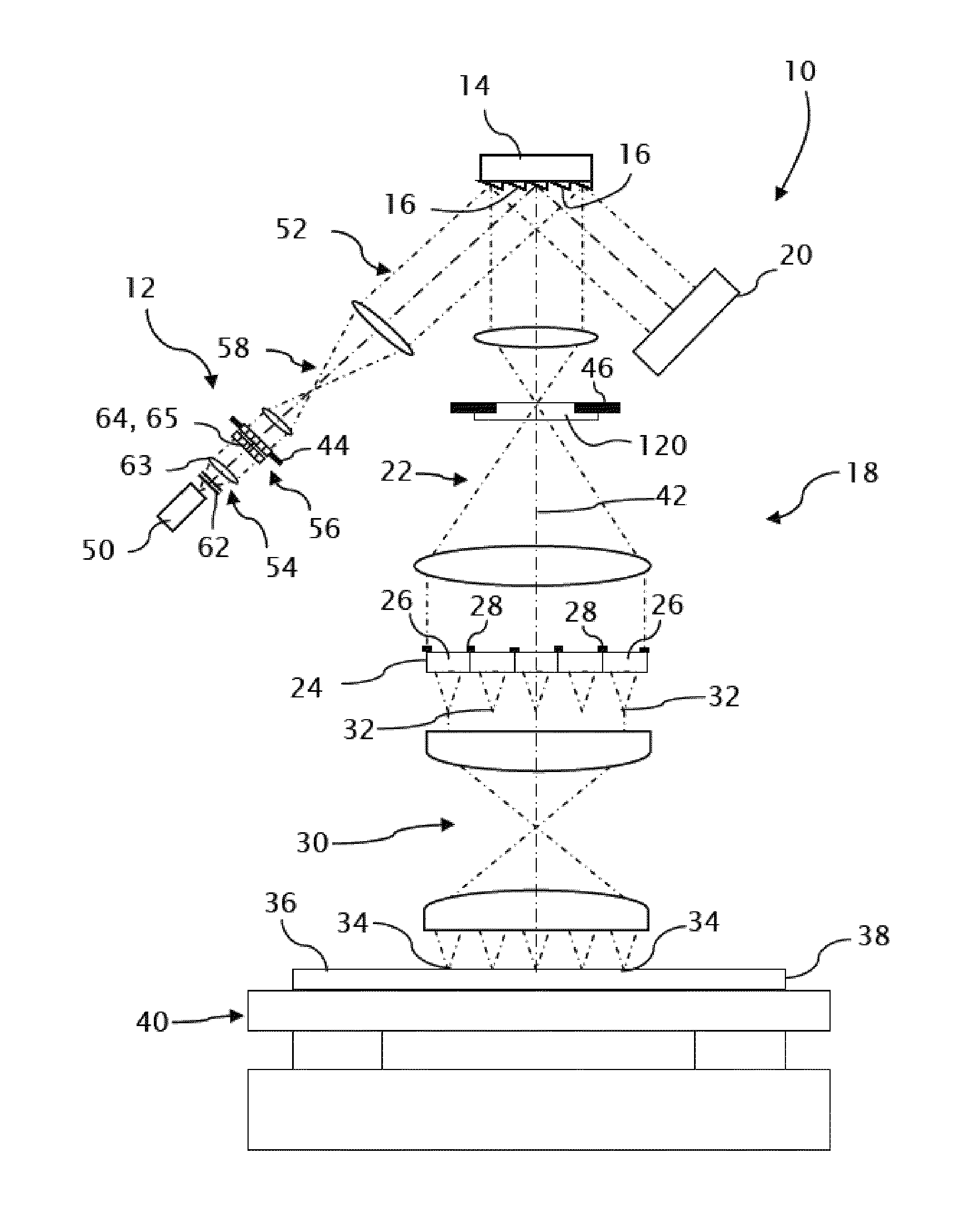
[0040]A microlithographic projection system 10, as an example of an active spot array projection system, is adapted in accordance with the invention for projecting patterns of well-formed spots. A pattern generator 14, including individually addressable elements 16, receives homogenized light from an illuminator 12 for directing discrete portions of the light to either a projector 18 or a beam dump 20, depending on the addressable states of the elements 16.

[0041]An imager 22 of the projector 18 images the addressable elements 16 of the pattern generator 14 onto corresponding microlenses 26 of a microlens array 24. A sufficient numerical aperture (e.g., 0.08 or higher) is chosen for the imager 22 to accurately reproduce magnified images of the addressable elements 16 on the microlenses 26 without significant crosstalk or overlap onto adjacent microlenses 26. Field stops 28 surround the entrance apertures of the microlenses 26 to block light from edges of the addressable elements 16. ...


PUM


Abstract

An active spot array projection system particularly for microlithographic projection includes a spatial light modulator, such as a digital micromirror device, having individually addressable elements. A focusing array, such as a microlens array, focuses elements transverse segments of the light beam into spots. Within an imaging optic between the spatial light modulator and the focusing array, an spatial frequency filter attenuates certain spatial frequencies of light arising from the irregularities of the individually addressable elements while avoiding attenuating higher spatial frequencies of light arising from the peripheral boundaries of the individually addressable elements for regulating light distributions of the spots while limiting crosstalk between adjacent spots.

Description

CROSS-REFERENCE TO RELATED APPLICATIONS[0001]This application claims the benefit of priority under 35 U.S.C. §119(e) of U.S. Provisional Application Ser. No. 61 / 085,387 filed on Jul. 31, 2008.TECHNICAL FIELD[0002]Microlithographic projection systems with addressable light modulating arrays project actively controlled patterns of spots onto photosensitive substrates. Such systems are particularly useful for manufacturing flat panel displays, printed circuit boards, micromechanical systems, and other microelectronic devices.BACKGROUND OF THE INVENTION[0003]Conventional microlithographic systems project images of masks (also referred to as reticles) onto photosensitive substrates. For projecting modified or even larger patterns, the masks must be replaced with other masks containing the different or extended patterns.[0004]So-called “maskless” or “reticle-free” microlithographic systems replace the masks with spatial light modulating arrays and projection systems for generating control...

Claims


Application Information

Patent Timeline
Patent Type & Authority Patents(United States)
IPC IPC(8): G03B27/72
CPCG03F7/70275G03F7/70308G03F7/70291G03F7/20
Inventor MICHALOSKI, PAUL FRANCIS
Owner CORNING INC
Features
  • R&D
  • Intellectual Property
  • Life Sciences
  • Materials
  • Tech Scout
  • Unparalleled Data Quality
  • Higher Quality Content
  • 60% Fewer Hallucinations
Learn More