
Audio outputting device, audio outputting method, noise reducing device, noise reducing method, program for noise reduction processing, noise reducing audio outputting device, and noise reducing audio outputting method

a technology audio output, which is applied in the field of audio outputting device, can solve the problems of difficult to check the noise reduction effect of each filter characteristic, inability to adapt to noise reduction, etc., and achieve excellent noise reduction effect, easy to check the effect of process, and change the effect of noise reduction characteristics

Active Publication Date: 2013-04-16
SONY CORP
View PDF16 Cites 13 Cited by
  • Summary
  • Abstract
  • Description
  • Claims
  • Application Information

AI Technical Summary

Benefits of technology

The present invention provides a process off period during which a process on an audio signal is typically stopped in effect once, which allows users to easily check the effect of the process. Additionally, the switching means can switch and change noise reducing characteristics according to various noise environments, resulting in an excellent noise reduction effect at all times. An effect off period during which sound unprocessed by a noise reducing process is typically output once is also provided, which allows users to easily check the effect of the noise reducing process.

Problems solved by technology

The active type noise reducing system in the past has a problem of being unable to perform noise reduction adapted to the noise environment characteristic of a place where the noise reduction is to be performed.
However, when a filter characteristic is switched in a state in which a noise reducing filter effect being produced, it is difficult to check the noise reduction effect of each filter characteristic.

Method used


Image

  • Audio outputting device, audio outputting method, noise reducing device, noise reducing method, program for noise reduction processing, noise reducing audio outputting device, and noise reducing audio outputting method
  • Audio outputting device, audio outputting method, noise reducing device, noise reducing method, program for noise reduction processing, noise reducing audio outputting device, and noise reducing audio outputting method
  • Audio outputting device, audio outputting method, noise reducing device, noise reducing method, program for noise reduction processing, noise reducing audio outputting device, and noise reducing audio outputting method

Examples


first embodiment

Noise Reducing Device of Feedback System

[0066]The embodiments of the noise reducing device according to the present invention to be described below have a configuration of a system that performs active noise reduction. Active noise reduction systems include a feedback system (feedback type) and a feedforward system (feedforward type). The present invention can be applied to both noise reduction systems.

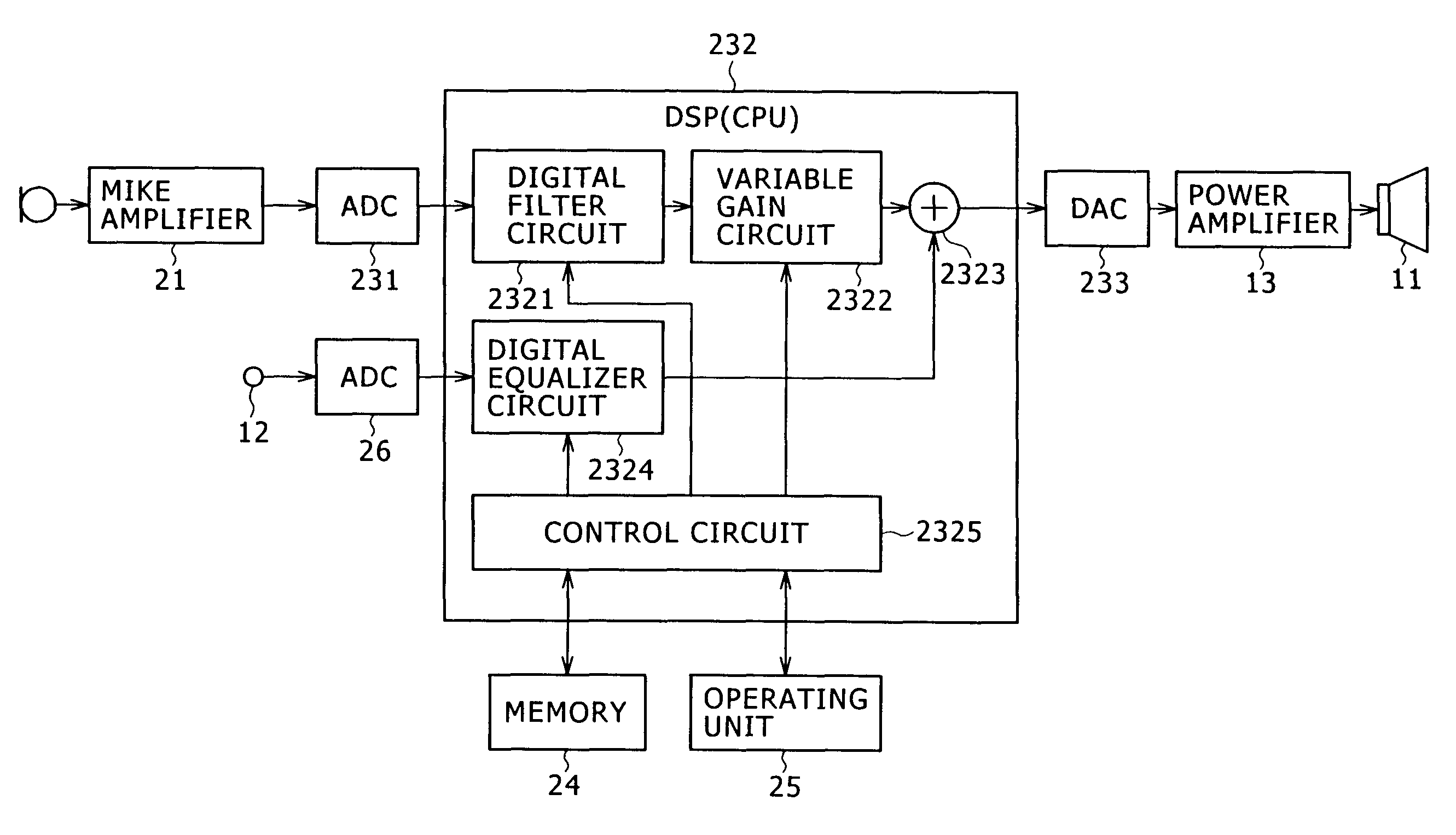
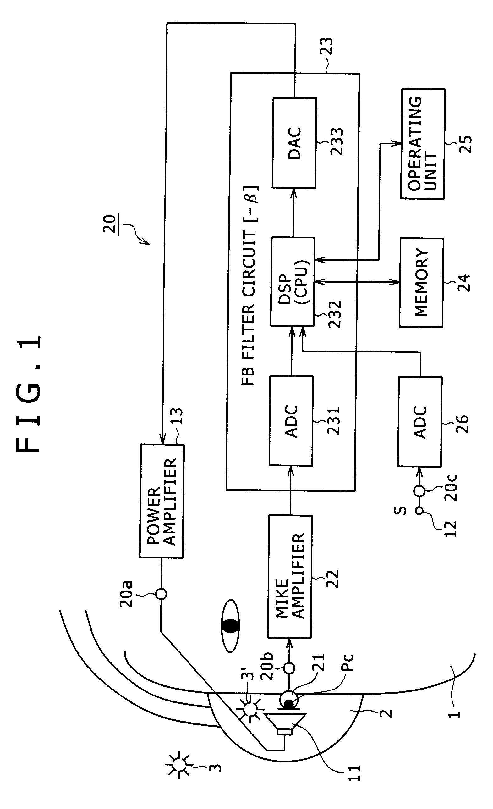
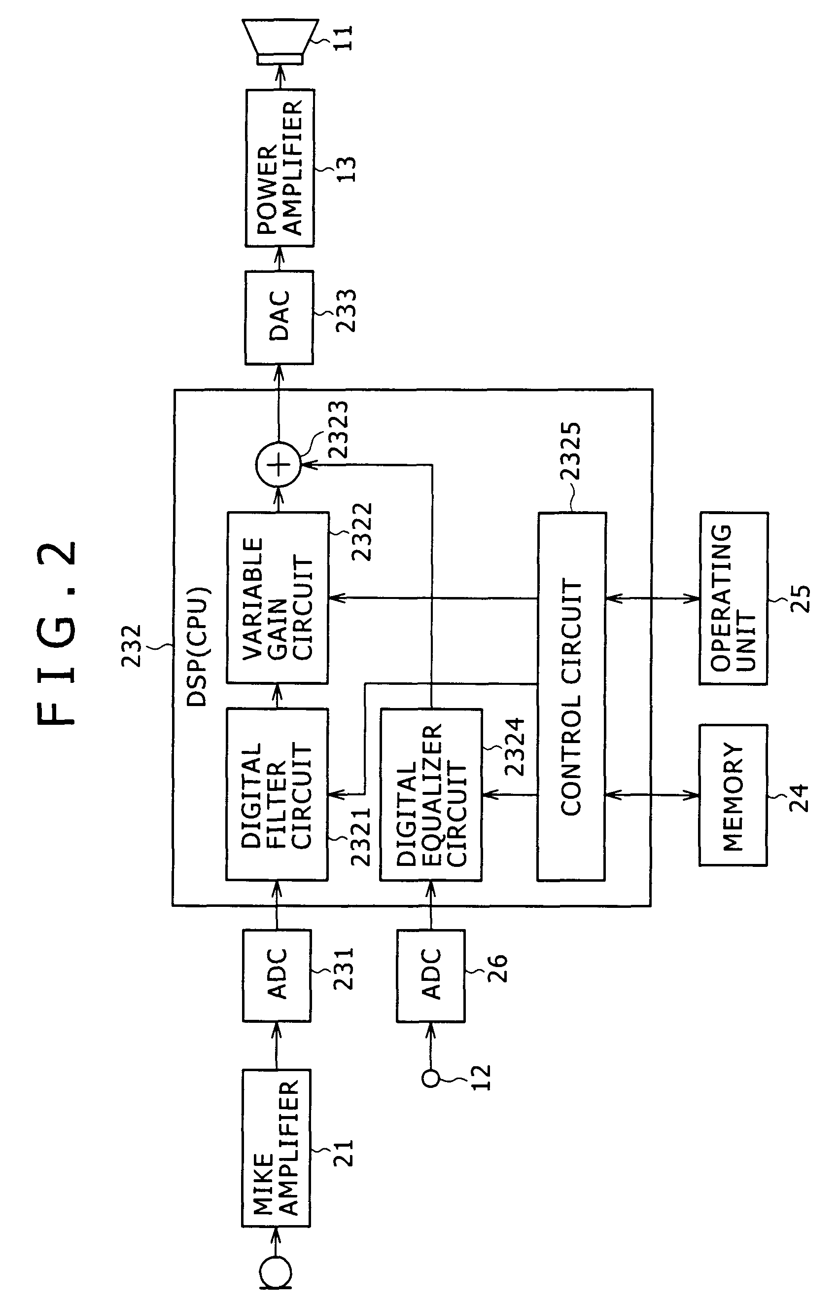
[0067]Description will first be made of an embodiment in which the noise reducing device according to the present invention is applied to a noise reducing system of a feedback type. FIG. 1 is a block diagram showing an example of configuration of an embodiment of a headphone device to which an embodiment of the noise reducing device according to the present invention is applied.

[0068]For simplicity of description, FIG. 1 shows the configuration of only a part of the headphone device for the right ear side of a listener 1. The same is true for embodiments to be described later. Inciden...

first example

[0125]FIG. 8 is a diagram of assistance in explaining a first example of the control of the control circuit 2325 at the mode switching and changing time in the present embodiment.

[0126]In this example, when determining that an operation of pressing the mode switching button is performed, the control circuit 2325 not only changes filter coefficients and switches NC filters formed in the digital filter circuit 2321, but also provides a noise reduction effect off interval A immediately after the operation of pressing the mode switching button is performed, the noise reduction effect off interval A being a predetermined time during which the noise reduction effect of the digital filter circuit 2321 is reduced to zero and thus the noise reduction effect is practically turned off, as shown in FIG. 8.

[0127]Then, the control circuit 2325 provides a noise reduction effect gradual increase interval B after the noise reduction effect off interval A is ended, the noise reduction effect gradual ...

second example

[0140]In this second example, the control at the time of switching and changing the noise mode which control is based on the operation of pressing the mode switching button as in the first example is performed, and at the same time, when the operation of pressing the mode switching button is performed, a noise mode after the mode switching change is notified to the user. Thereby the user can recognize the noise mode close to a noise environment in which the user is located in advance, and check the noise reduction effect.

[0141]In this case, for the notification of the noise mode, the second example uses for example a method of adding a voice message notifying each noise mode to the audio signal supplied to the driver 11. For example, a notifying voice message such as “airplane” or the like is used when a next noise mode set by a switching change is the airplane mode, a notifying voice message such as “train” or the like is used when a next noise mode set by a switching change is the...


PUM


Abstract

Disclosed herein is an audio outputting device for switching a plurality of processes to perform a process on an audio signal, and acoustically reproducing and outputting the audio signal, the audio outputting device including, a control section for, when changing a process performed on an audio signal from one process to another process, stopping the one process on the audio signal, outputting sound based on the audio signal unprocessed by either of the one process and the other process, and performing the other process on the audio signal after passage of a predetermined period of time.

Description

CROSS REFERENCES TO RELATED APPLICATIONS[0001]The present invention contains subject matter related to Japanese Patent Application JP 2006-350961 filed in the Japan Patent Office on Dec. 27, 2006, the entire contents of which being incorporated herein by reference.BACKGROUND OF THE INVENTION[0002]1. Field of the Invention[0003]The present invention relates to an audio outputting device such for example as a headphone device and a noise reducing audio outputting device. The present invention also relates to a noise reducing device used in these devices and a program for noise reduction processing.[0004]2. Description of the Related Art[0005]With the spread of portable type audio players, a noise reducing system that reduces noise of an external environment and thus provides a listener with a good reproduced sound field space in which the external noise is reduced has begun to be spread for use in headphones and earphones for the portable type audio players.[0006]An example of this ki...

Claims


Application Information

Patent Timeline
Patent Type & Authority Patents(United States)
IPC IPC(8): G10K11/16H03G9/00G10L21/0208
CPCG10K11/178H04R1/1083H04R1/1041H04R5/033G10K11/1783G10K11/17873G10K11/17885G10K11/17881G10K11/17875G10K11/17821G10K11/17817G10K11/17853
Inventor ASADA, KOHEISASAKI, TORU
Owner SONY CORP
Learn More