
Head-end circuit and remote antenna unit and hybrid wired/wireless network system and transceiving method using thereof

a head-end circuit and antenna unit technology, applied in multiplex communication, electromagnetic transmission, electrical equipment, etc., can solve the problems of low data transmission bandwidth, low transmission speed, and inability to support roaming connection,

Active Publication Date: 2013-04-16
IND TECH RES INST
View PDF9 Cites 37 Cited by
  • Summary
  • Abstract
  • Description
  • Claims
  • Application Information

AI Technical Summary

Benefits of technology

This approach enhances transmission quality and stability in long distances by minimizing signal fading and time-shifting, enabling high-bandwidth and mobile data transmission.

Problems solved by technology

In the present technique, wired fiber network is advantageously with high data transmission bandwidth and is disadvantageously incapable of supporting roaming connection and with low mobility.
Wireless network, however, is advantageously capable of supporting roaming connection and with high mobility and is disadvantageously with low data transmission bandwidth and low transmission speed, which is incapable of meeting the demand of multimedia data transmission speed increased with each passing day.
Therefore, conventional RoF technique employing double sideband modulation approach has the problem of signal fading resulted in low transmission quality in long transmission distance situations; conventional RoF technique employing single sideband modulation approach has the problem of signal time-shifting resulted in low and unstable transmission quality in long transmission distance situations.

Method used


Image

  • Head-end circuit and remote antenna unit and hybrid wired/wireless network system and transceiving method using thereof
  • Head-end circuit and remote antenna unit and hybrid wired/wireless network system and transceiving method using thereof
  • Head-end circuit and remote antenna unit and hybrid wired/wireless network system and transceiving method using thereof

Examples


Embodiment Construction

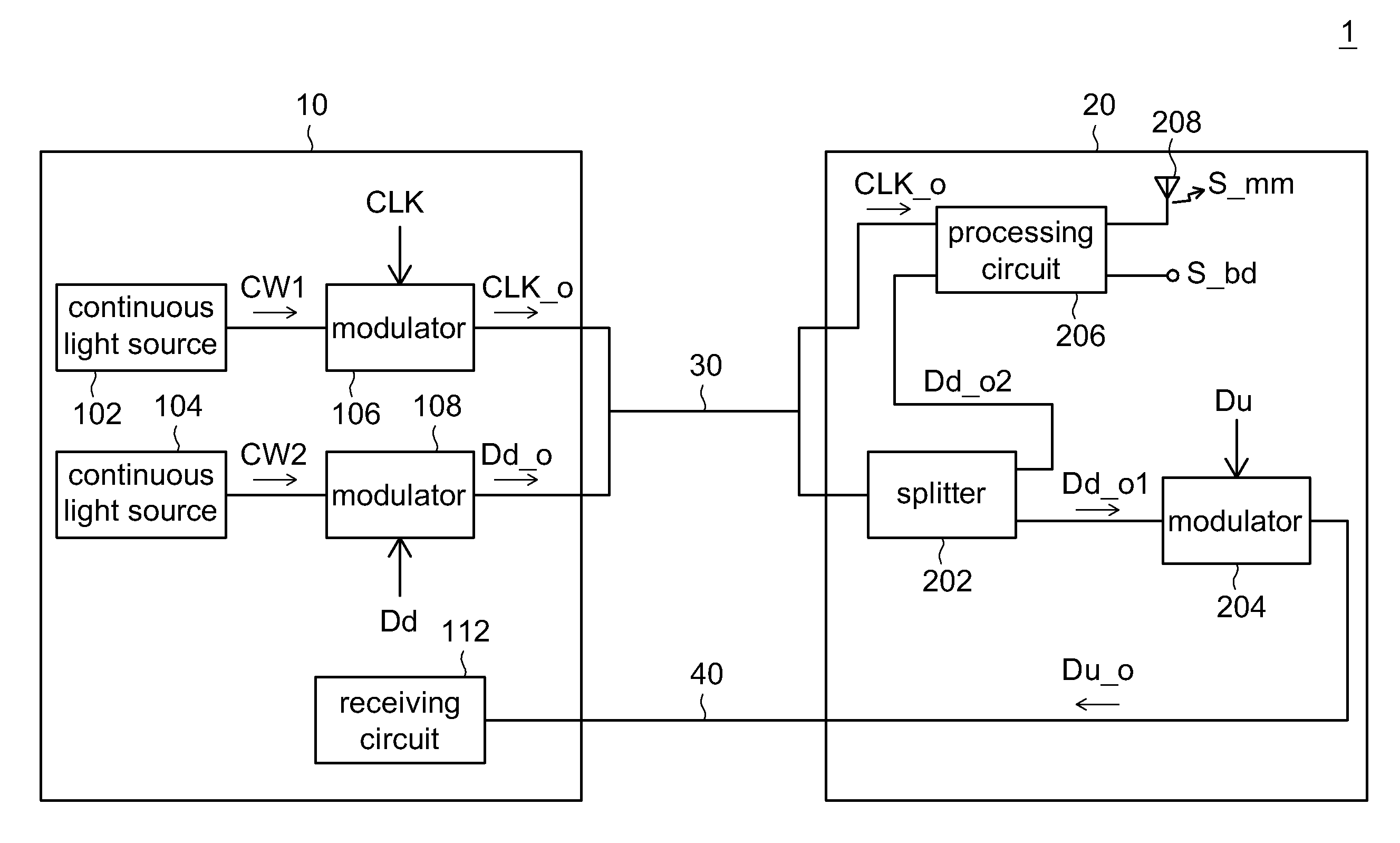
[0019]The hybrid wired / wireless network system employs independent optical signal for transmission of clock signal.

[0020]The hybrid wired / wireless network system according to an embodiment of the invention employs two set of optical signals, which correspond to different wavelengths as carrier waves for the respective transmissions of an optical clock signal and downlink data. Thus, mutual interference between the optical signal conveying baseband signal and that conveying microwave signal can be reduced. Therefore, in comparison to network systems employing the conventional radio over fiber (RoF) technique, the hybrid wired / wireless network system is advantageously capable of reducing signal fading and signal time-shifting taking place in fiber paths and with high transmission quality and stability in long transmission distance situations.

[0021]Referring to FIG. 1, a block diagram of the hybrid wired / wireless network system according to an exemplary embodiment consistent with the i...


PUM


Abstract

A head-end circuit comprises first and second continuous light sources, first and second modulators. The first and the second continuous light sources provide first and second optical signals respectively corresponding to first wavelength and second wavelength, which is different from the first wavelength. The first modulator modulates the first optical signal based on first clock signal to generate an optical clock signal. The second modulator modulates the second optical signal based on downlink data to generate optical downlink data with the carrier of the second optical signal. The optical clock signal and the optical down link data are outputted to a remote antenna unit via first fiber path.

Description

[0001]This application claims the benefit of Taiwan application Serial No. 98125501, filed Jul. 29, 2009, the subject matter of which is incorporated herein by reference.BACKGROUND[0002]1. Technical Field[0003]The invention relates in general to a wired / wireless network system, and more particularly to a wired / wireless network system capable of performing radio over fiber (RoF) operation.[0004]2. Description of the Related Art[0005]In the present technique, wired fiber network is advantageously with high data transmission bandwidth and is disadvantageously incapable of supporting roaming connection and with low mobility. Wireless network, however, is advantageously capable of supporting roaming connection and with high mobility and is disadvantageously with low data transmission bandwidth and low transmission speed, which is incapable of meeting the demand of multimedia data transmission speed increased with each passing day.[0006]Thus, hybrid wired / wireless network system capable o...

Claims


Application Information

Patent Timeline
Patent Type & Authority Patents(United States)
IPC IPC(8): H04B10/00H04J14/00
CPCH04B10/25759
Inventor YEH, CHIEN-HUNGCHOW, CHI-WAICHI, SIEN
Owner IND TECH RES INST
Learn More