Hydraulic flow sharing system for excavating and pipe laying work

a technology of hydraulic flow and excavating, which is applied in the direction of mechanical equipment, couplings, cranes, etc., can solve the problems of severe safety accidents, declination of equipment, and pipe layer collapse, so as to prevent the shaking of pulled objects due to inertia, improve work efficiency, and improve operator's convenience in traveling manipulation

Inactive Publication Date: 2013-04-23
VOLVO CONSTR EQUIP HLDG SWEDEN AB
View PDF5 Cites 10 Cited by
  • Summary
  • Abstract
  • Description
  • Claims
  • Application Information

AI Technical Summary

Benefits of technology

[0012]Embodiments of the present invention relate to a hydraulic flow sharing system for excavating and pipe laying work, which can prevent the occurrence of an abrupt change of a traveling speed during traveling and thus can prevent the shaking of a pulled object due to inertia through compulsory sharing of the flow rate being applied to a working device or a traveling apparatus when a combined operation, in which the traveling apparatus and the working device, such as a boom for pulling up an oil pipe, are simultaneously driven, is performed.
[0013]Embodiments of the present invention relate to a hydraulic flow sharing system for excavating and pipe laying work, which can improve the work efficiency through heightening of a traveling speed when an excavating work is performed, and which can prevent the damage of an oil pipe that shakes due to inertia and the occurrence of safety accidents through prevention of an abrupt change of the traveling speed when a pipe laying work is performed.
[0014]In one aspect of the present invention, there is provided a hydraulic flow sharing system for excavating and pipe laying work, which includes first and second variable displacement hydraulic pumps and a pilot pump connected to an engine; a left traveling motor and a boom cylinder connected to the first hydraulic pump; control valves installed in a center bypass path of the first hydraulic pump, and shifted to control the flow direction and flow amount of hydraulic fluid being supplied to the left traveling motor and the boom cylinder; a right traveling motor, a swing motor, and a winch motor connected to the second hydraulic pump; control valves installed in a center bypass path of the second hydraulic pump, and shifted to control the flow direction and flow amount of hydraulic fluid being supplied to the right traveling motor, the swing motor, and the winch motor; a straight traveling valve installed on an upstream side of the center bypass path of the first hydraulic pump, and shifted, in response to a signal pressure applied from an outside when a work mode for simultaneously driving the boom cylinder, the swing motor, the winch motor, and the left and right traveling motors is selected, to share and supply the hydraulic fluid fed from the first hydraulic pump to the control valves for the boom cylinder, the swing motor, and the winch motor, and to share and supply the hydraulic fluid fed from the second hydraulic pump to the control valves for the left and right traveling motors, respectively; an unloading valve open, in response to the signal pressure for shifting the straight traveling valve, to prevent the occurrence of overload in the center bypass paths of the first and second hydraulic pumps; and a selection valve releasing an unloading function of the corresponding unloading valve when any one of the boom cylinder, the swing motor, the winch motor, and the left and right traveling motors is driven in a shift mode of the straight traveling valve.
[0020]With the above-described construction, the hydraulic flow sharing system for excavating and pipe laying work according to the embodiments of the present invention has the following advantages.
[0021]The shaking of a pulled object due to inertia can be prevented through prevention of an abrupt change of a traveling speed during traveling when a combined operation, in which a traveling apparatus and a working device are simultaneously driven, is performed, and thus operator's convenience in traveling manipulation can be improved.
[0022]Also, the work efficiency can be improved through heightening of a traveling speed when an excavating work is performed, and the damage of an oil pipe that shakes due to inertia and the occurrence of safety accidents can be prevented through prevention of an abrupt change of the traveling speed when a pipe laying work is performed.

Problems solved by technology

In the case where the pipe layer travels or performs a swing operation at high speed or the traveling speed is abruptly increased or decreased, fatal problems may occur on the pipe layer.
In the case of driving the working device in a state where a traveling operation is performed, declination of the equipment may occur due to an unbalanced state of hydraulic fluid being supplied to the respective traveling motors.
On the other hand, in the case of the excavator, a safety accident such as in the pipe layer may not occur due to the structural characteristic of the working devices, such as a boom, an arm, and the like, composed of rigid members even if the traveling speed is abruptly changed during traveling.
However, if the traveling speed is abruptly changed during traveling in a state where the pipe layer pulls up the oil pipe, the oil pipe shakes in a traveling direction of the equipment due to inertia, and severe safety accident may occur.
In this case, the oil may collide with a part of the equipment neighboring the oil pipe or may secede from a wire rope and fall down.

Method used


Image

  • Hydraulic flow sharing system for excavating and pipe laying work
  • Hydraulic flow sharing system for excavating and pipe laying work
  • Hydraulic flow sharing system for excavating and pipe laying work

Examples


Embodiment Construction

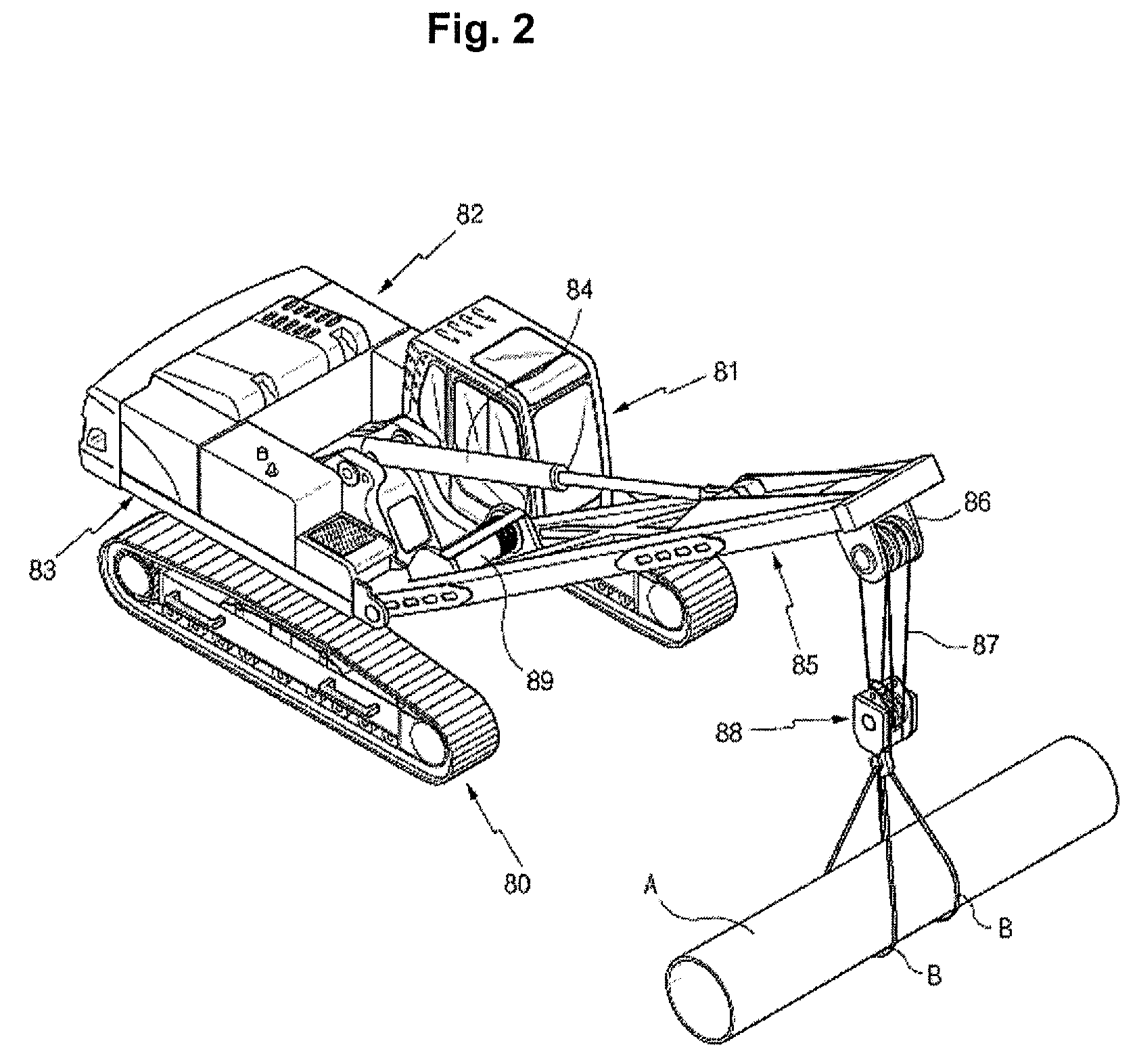
[0026]Hereinafter, preferred embodiments of the present invention will be described with reference to the accompanying drawings. The matters defined in the description, such as the detailed construction and elements, are nothing but specific details provided to assist those of ordinary skill in the art in a comprehensive understanding of the invention, and thus the present invention is not limited thereto.

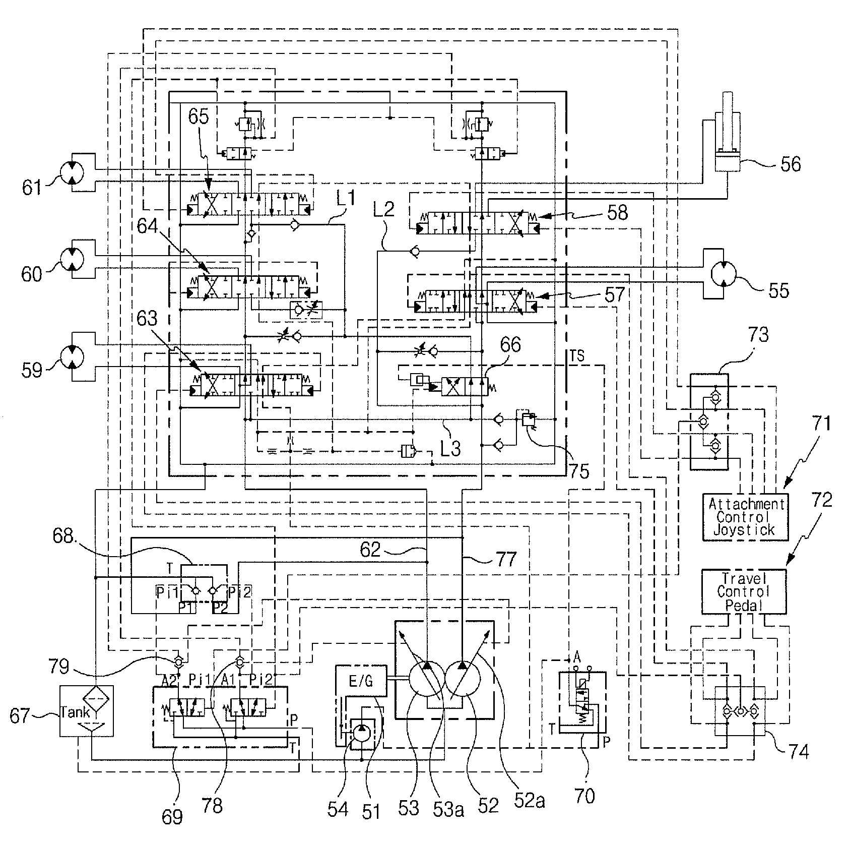
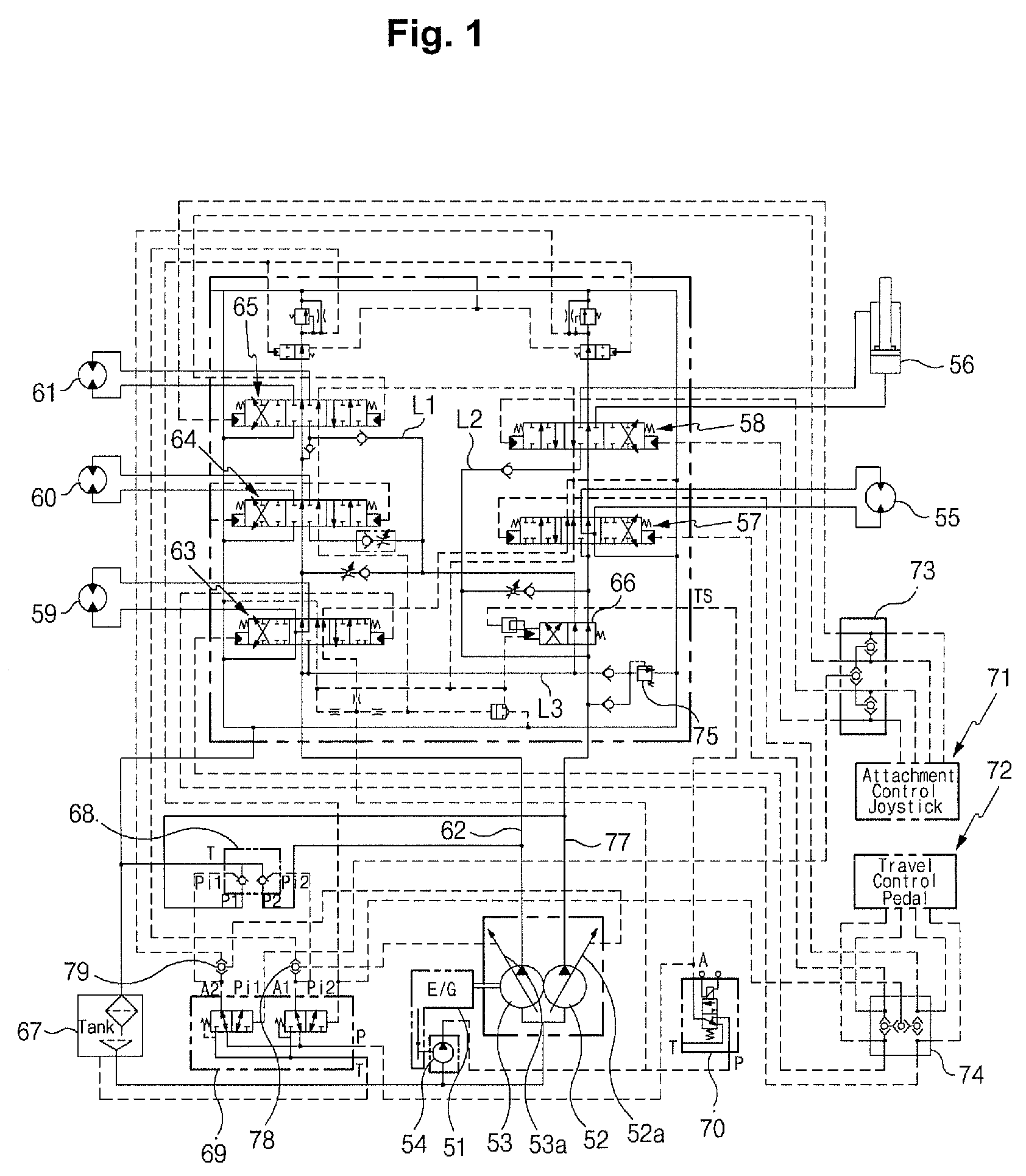
[0027]As illustrated in FIGS. 1 and 2, a hydraulic flow sharing system for excavating and pipe laying work according to an embodiment of the present invention includes first and second variable displacement hydraulic pumps 52 and 53 and a pilot pump 54 connected to an engine 51; a left traveling motor 55 and a boom cylinder 56 connected to the first hydraulic pump 52; control valves 57 and 58 installed in a center bypass path 77 of the first hydraulic pump 52, and shifted to control the flow direction and flow amount of hydraulic fluid being supplied to the left traveling motor 55 ...


PUM


Abstract

A hydraulic flow sharing system for excavating and pipe laying work is provided, which can prevent the abrupt change of a traveling speed during traveling through compulsory sharing of the flow rate applied to a working device and a traveling apparatus when a combined operation, in which the traveling apparatus and the working device such as a boom are simultaneously driven, is performed.

Description

CROSS-REFERENCE TO RELATED APPLICATION[0001]This application is based on and claims priority from Korean Patent Application No. 10-2008-0077746, filed on Aug. 8, 2008 in the Korean Intellectual Property Office, the disclosure of which is incorporated herein in its entirety by reference.FIELD OF THE INVENTION[0002]The present invention relates to a hydraulic flow sharing system for excavating and pipe laying work, which can prevent an abrupt change of a traveling speed of a traveling apparatus when a pipe laying work for pulling up and carrying a heavy oil pipe is performed through replacement of working devices (e.g. a boom, a winch, and the like).[0003]More particularly, the present invention relates to a hydraulic flow sharing system for excavating and pipe laying work, which can prevent the occurrence of an abrupt change of a traveling speed during traveling through compulsory sharing of the flow rate being applied to a working device or a traveling apparatus when a combined oper...

Claims


Application Information

Patent Timeline
Patent Type & Authority Patents(United States)
IPC IPC(8): F16D31/02
CPCB66C23/44E02F9/2239E02F9/2207E02F5/10E02F9/20E02F9/22
Inventor CHOI, HAN OKLEE, KYUNG SUB
Owner VOLVO CONSTR EQUIP HLDG SWEDEN AB
Why Eureka
Try Eureka