Direct-injection type engine

a direct injection and engine technology, applied in the direction of combustion engines, fuel injection apparatus, charge feed systems, etc., can solve the problems of increased smoke discharge, increased amount of unburned hydrocarbon discharge at the cold engine start condition, and increased smoke discharge, etc., to facilitate the root portion of the fuel spray, reduce the effect of intake resistance and small pumping loss

Inactive Publication Date: 2013-04-23
TOYOTA JIDOSHA KK
View PDF27 Cites 8 Cited by
  • Summary
  • Abstract
  • Description
  • Claims
  • Application Information

AI Technical Summary

Benefits of technology

[0008]In consideration of the above situation, the object of the invention is to provide a direct-injection engine wherein fuel is injected during the latter half of the compression stroke and the diffusion of the root portion of the fuel spray can be facilitated without using the impingement of the root portion of the fuel spray on the wall surface.
[0025]The above-explained constitution is based on this knowledge. According to this, the intake resistance can be totally decreased, compared with the case that two helical or tangential ports are used as explained above. As a result, the fuel consumption of the engine is improved. Further, the amount of the air introduced into the cylinder during the high engine load can be increased and as a result, the maximum output of the engine is increased.

Problems solved by technology

In particular, at the root portion of the fuel spray, the diffusion (i.e. the mixture of the fuel and the air) is difficult to be facilitated in a sufficient manner even by using the swirl due to the large fuel density.
Further, at the complete warmed engine condition, etc., an amount of the discharge of smoke may be increased due to the incomplete combustion at the root portion.
Also according to this, similar to the above, the problems such as the increase of the amount of the discharge of the unburned hydrocarbon at the cold engine start condition, etc. and the increase of the amount of the discharge of the smoke at the complete warmed engine condition, etc. may be raised.

Method used


Image

  • Direct-injection type engine
  • Direct-injection type engine
  • Direct-injection type engine

Examples


Embodiment Construction

[0034]Below, embodiments of a direct-injection type engine (a diesel engine) according to the invention will be explained by referring to the drawings.

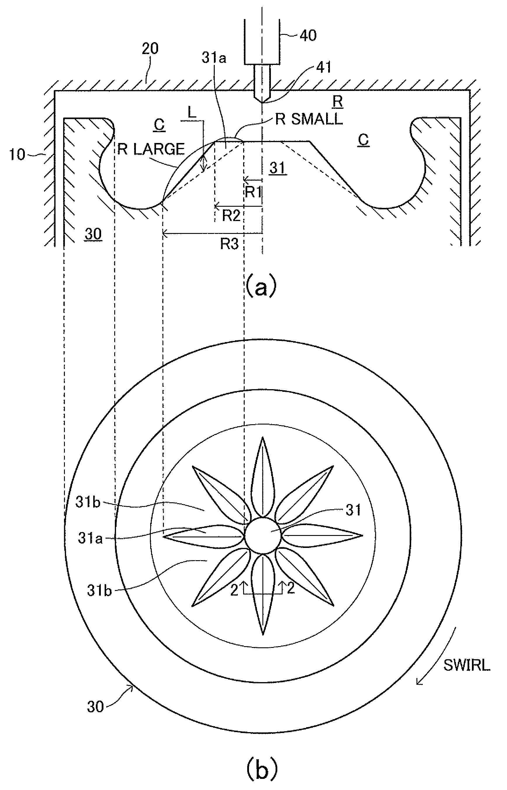
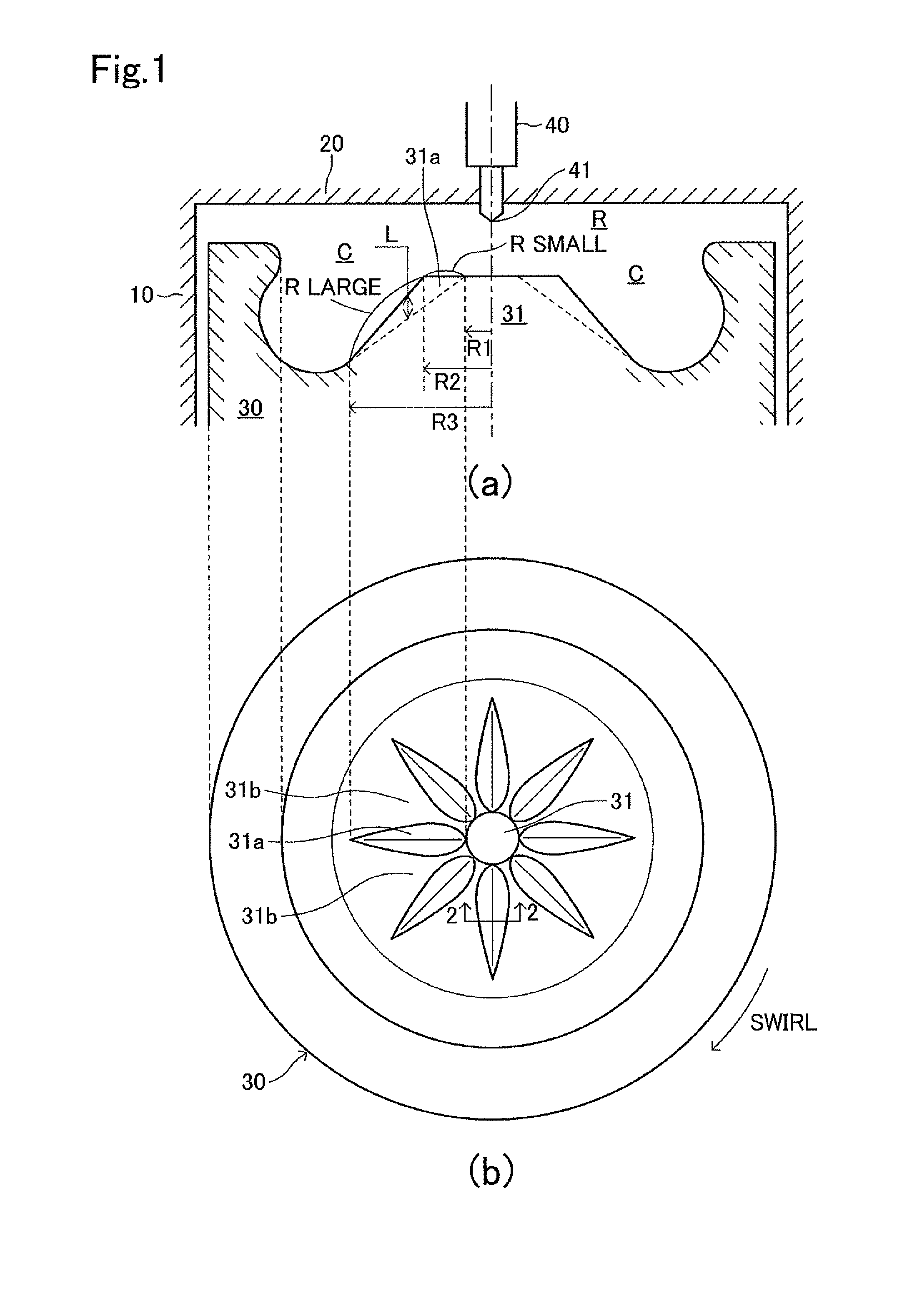
[0035]FIG. 1(a) is a longitudinal sectional view showing a general constitution around a combustion chamber of this embodiment. FIG. 1(a) is a plane view (a top view) of a piston. In this engine, an inner wall (a cylindrical surface) of a cylinder 10, an inner wall (a plane surface) of a cylinder head portion 20 and a top portion of a piston 30 define and form a combustion chamber R.

[0036]A fuel injector 40 for injecting fuel from injection bores 41 directly into the combustion chamber R is secured in the cylinder head portion 20. The fuel injector 40 is positioned such that an axis of the fuel injector is aligned with a central axis of the cylinder 10 (or the piston 30).

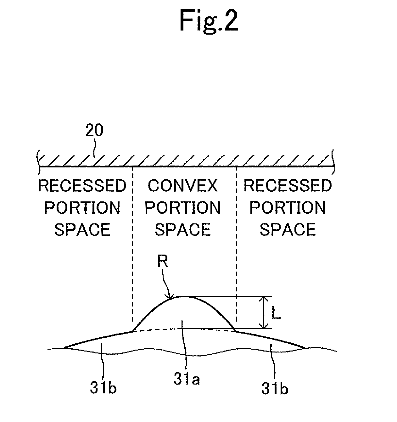
[0037]A cavity C (a recess) is formed in the top portion of the piston 30, coaxially with the piston 30 and a truncated-cone-shaped land portion 31 (a protruded porti...


PUM


Abstract

A plurality of convex portions are radially fanned and spaced apart from each other by a constant angle in a planar view on a tapered surface of a land portion formed on a bottom surface of a cavity formed in a top portion of a piston. Each convex portion is positioned such that the extending direction of the convex portion aligns with an axis X of a corresponding fuel spray. Thereby, each fuel spray moves forward through a space (convex portion space) between the corresponding convex portion and an inner wall of a cylinder head portion along the extending direction of the corresponding convex portion. When a fuel injection is performed during the latter half of a compression stroke, a pressure in a convex portion space is increased, compared with a pressure in a space of the other portion by the decrease of a ratio of the volume of the convex portion space relative to the volume of the space of the other portion by the proceeding of the compression by the piston. Each fuel spray is circumferentially expanded by the pressure difference.

Description

TECHNICAL FIELD[0001]The invention relates to a direct-injection type engine.BACKGROUND ART[0002]Conventionally, a direct-injection type engine (a diesel engine or a spark ignition type engine) provided with a fuel injector for injecting fuel directly into a combustion chamber, in which a fuel injection is performed during the latter half of a compression stroke, is known. In this engine, it is effective to facilitate the mixture of fuel and air in the combustion chamber in order to decrease an amount of discharged emission.[0003]To this end, for example, in a diesel engine described in the Unexamined Japanese Patent Publication No. 7-208173, a land portion (a protruded portion) is provided on a central portion of a bottom surface of a cavity provided in a top portion of a piston and a plurality of convex portions extending in a direction perpendicular to an axis of a fuel spray and a plurality of recessed portions extending in the direction perpendicular to the axis of the fuel spr...

Claims


Application Information

Patent Timeline
Patent Type & Authority Patents(United States)
IPC IPC(8): F02F3/26F02F3/00
CPCF02B23/0651F02B23/0669F02B23/0672F02B2023/108F02M61/1806Y02T10/125Y02T10/146F02B23/0624F02B23/0687F02B23/101F02B2023/103F02B2031/006F02B2275/14Y02T10/12
Inventor HASEGAWA, RYO
Owner TOYOTA JIDOSHA KK
Why Eureka
Try Eureka