Transaxle

a technology of transaxles and axles, applied in the field of transaxles, can solve the problems of increasing costs, requiring a large amount of power, and the shift mechanism has to be minute and complicated, so as to reduce the rotary speed of the axle, increase the variation of the speed and torque of the axle, and reduce the transmission

Active Publication Date: 2013-04-23
KANZAKI KOKYUKOKI MFG
View PDF42 Cites 29 Cited by
  • Summary
  • Abstract
  • Description
  • Claims
  • Application Information

AI Technical Summary

Benefits of technology

[0015]Therefore, due to the coaxial arrangement of the motor output shaft with the axle, the transaxle is minimized in the radial direction of the motor output shaft and the axle so as to be adaptable as a wheel hub drive unit. While the speed changing planetary gear transmission includes two speed gear trains, i.e., the high and low speed gear trains, for transmitting power from the motor output shaft to the carrier, the only shifter serves as a member axially slidable along the motor output shaft so as to constitute a shift mechanism for selecting whether the high or low speed gear train transmits power from the motor output shaft to the axle, i.e., for selecting either a high or low speed state of the speed changing planetary gear transmission. Further, due to the axial sliding of the shifter on the motor output shaft and the arrangement of the high and low sun gears on the motor output shaft, to constitute the shift mechanism for realizing the high or low speed state of the speed changing planetary gear transmission by the engagement of the shifter with the at least one of the high and low speed sun gears, only the shifter and the at least one of the high and low sun gears need to be formed to have a structure for engaging with each other, however, the structure can be simple, e.g., a slidable key and a key groove or spline-teeth. In this way, the shift mechanism of the transaxle adaptable as the wheel hub drive unit according to the present invention is simplified and economized in comparison with the complicated shift mechanism of the conventional wheel hub drive unit disclosed in Reference 3 including three slidable members, i.e., the shift drum and both the clutch members, whose respective slide positions have to be set to realize each of the high and low speed states of the speed changing transmission.
[0056]Alternatively, in some embodiments, the axle is paired, and the transaxle further comprises a differential unit differentially connecting the pair of axles to each other. Therefore, while the multiple motor generator unit applies its total motor output torque equally onto the respective axles, the differential unit allows differential rotation of the axles so as to ensure smooth turning or curving of the vehicle. Further, to drive a pair of drive wheels of a vehicle, the transaxle does not have to be paired, thereby reducing components and costs.

Problems solved by technology

In other words, the shift mechanism has to be minute and complicated so as to increase costs because it has to realize rotational positions of the first and second shift levers corresponding to the respective high-speed, low-speed and neutral positions of the shift drum so as to achieve the above-mentioned engagement / disengagement states of the ring gear clutch member with or from the ring gear and of the carrier clutch member with or from the planetary gear carrier.

Method used


Image

  • Transaxle
  • Transaxle
  • Transaxle

Examples


Embodiment Construction

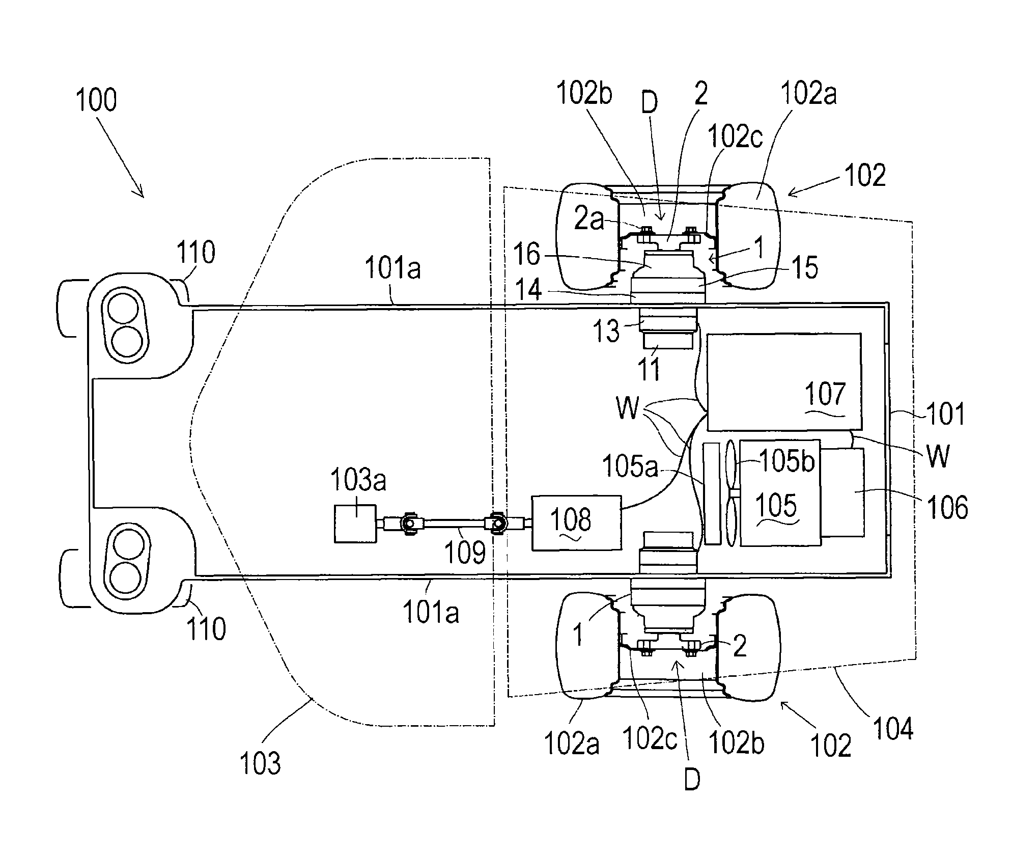
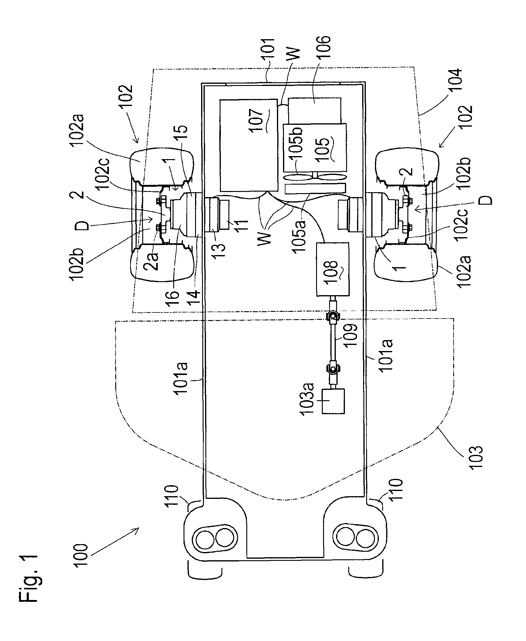
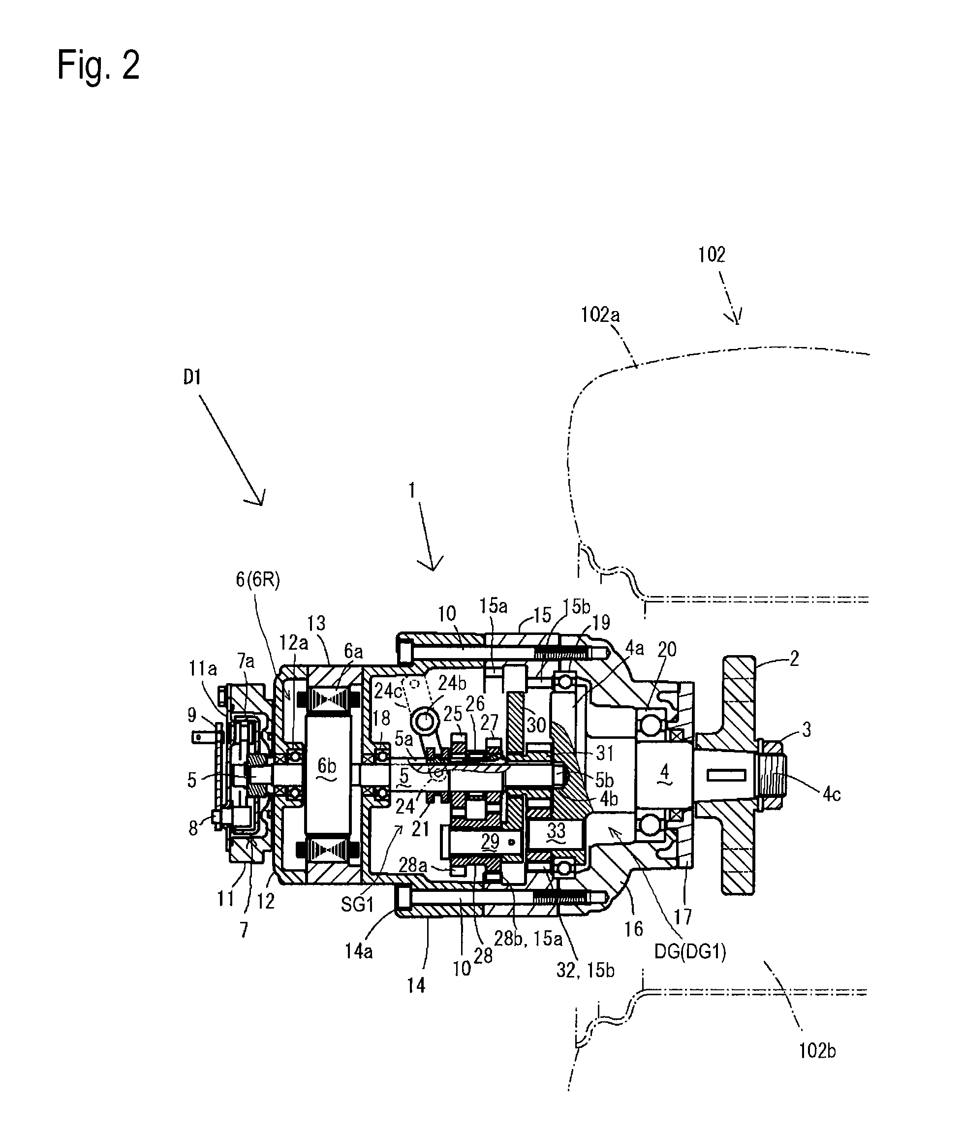
[0097]Description will be given of a lawn mower 100 serving as an embodiment of a vehicle equipped with right and left wheel hub drive units D with reference to FIG. 1. Lawn mower 100 includes right and left drive wheels (rear wheels) 102, and is equipped with right and left wheel hub drive units D for driving respective right and left drive wheels 102. Each wheel hub drive unit D includes a hub casing 1 incorporating a motor, a speed changing transmission and so on, as discussed later. Hub casing 1 journals a later-discussed axle 4 (see FIG. 2). A hub 2 is fixed on axle 4 so as to serve as a hub of drive wheel 102.

[0098]Hub casings 1 of respective right and left wheel hub drive units D are fixed to respective right and left side plate portions 101a of a vehicle body frame 101 of lawn mower 100. Hub casings 1 project laterally distally from respective side plate portions 101a. Axles 4 project outward from laterally distal ends of respective hub casings 1, and hubs 2 fixed on the lat...


PUM


Abstract

A transaxle includes an axle and a multiple motor generator unit for driving the axle. The multiple motor generator unit includes a common rotor shaft drivingly connected to the axle, armature windings serving as a first stator and a second stator aligned opposite each other in the axial direction of the rotor shaft, a common rotor member fixed on the rotor shaft, and permanent magnets provided on the common rotor member so as to serve as a first rotor facing the first stator, and as a second rotor facing the second stator. The first stator and the first rotor constitute a first motor generator. The second stator and the second rotor constitute the second motor generator. A total motor output torque of the first and second motor generators for rotating the rotor member and the rotor shaft can be changed in correspondence to a load applied from the axle to the rotor shaft.

Description

BACKGROUND OF THE INVENTION[0001]1. Field of the Invention[0002]The present invention relates to transaxles, each of which includes an axle and a motor for driving the axle and has a function to change rotary speed or torque of the axle. A wheel hub drive unit to be attached to a hub of a single wheel serves as one of the transaxles. The wheel hub drive unit is integrally provided with a single axle to be drivingly connected to the wheel, and with a motor for driving the axle. The wheel hub drive unit is further integrally provided with a mechanical speed changing transmission, such as a gear transmission, interposed between the motor and the axle so as to change the rotary speed or torque of the axle. Additionally or alternatively, the wheel hub drive unit is provided with a plurality of motor generators serving as the motor so that the motor generators output variable torque for changing the rotary speed or torque of the axle. Another transaxle is provided with a pair of axles to ...

Claims


Application Information

Patent Timeline
Patent Type & Authority Patents(United States)
IPC IPC(8): B60K17/12
CPCB60K6/26B60K7/0007B60K7/0015B60K17/046B60W10/08H02K7/116B60K6/46B60K17/06B60K2001/001B60K2007/0038B60K2007/0092B60L2240/423B60W20/00B60W2510/083B60W2520/10B60W2520/28B60W2540/10B60Y2200/223H02K7/14Y02T10/6217Y02T10/641Y02T10/642B60L15/2054B60L2220/52B60L2240/12B60L2240/461B60L2240/507B60L2250/26Y02T10/72B60L50/62B60L50/16Y02T10/62Y02T10/64Y02T10/7072Y02T10/70B60W2540/18
Inventor ISHII, NORIHIRO
Owner KANZAKI KOKYUKOKI MFG
Why Eureka
Try Eureka