Aluminum roof panel for attachment to supporting steel vehicle body members

a technology for aluminum roof panels and steel vehicles, applied in the direction of roofs, transportation and packaging, vehicle arrangements, etc., can solve problems such as unacceptable customer behavior, and achieve the effect of reducing or eliminating distortion in aluminum roofs

Active Publication Date: 2013-04-23
GM GLOBAL TECH OPERATIONS LLC
View PDF20 Cites 30 Cited by
  • Summary
  • Abstract
  • Description
  • Claims
  • Application Information

AI Technical Summary

Benefits of technology

[0013]If an aluminum roof stamping is to be attached to a predominantly steel vehicle body, a suitable joining practice is to use rivets, usually self-piercing rivets, applied through the roof flange and engaging the steel mounting surfaces below, to secure the roof flange to the body mounting surfaces. The rivets are often supplemented by adhesive applied to the faying surfaces of the roof flange and the body mounting surfaces. Sufficient adhesive is applied to effect bonding across the entire flange width to maximize the strength of the adhesive bond.
[0020]It is intended that both these modifications to the stamped roof design be applied in conjunction so that they may operate cooperatively to reduce or eliminate distortion in aluminum roofs attached to steel vehicle bodies.

Problems solved by technology

This approach, though appealing from a vehicle mass-reduction viewpoint, raises issues due to the significantly different coefficients of thermal expansion of aluminum and steel—about 23×10−6 K−1 for aluminum and about 11×10−6 K−1 for steel.
Since plastic deformation is not reversed on cooling, any such deformation may result in an appearance feature such as a crease or buckle in the roof which would be unacceptable to the customer.

Method used


Image

  • Aluminum roof panel for attachment to supporting steel vehicle body members
  • Aluminum roof panel for attachment to supporting steel vehicle body members
  • Aluminum roof panel for attachment to supporting steel vehicle body members

Examples


Embodiment Construction

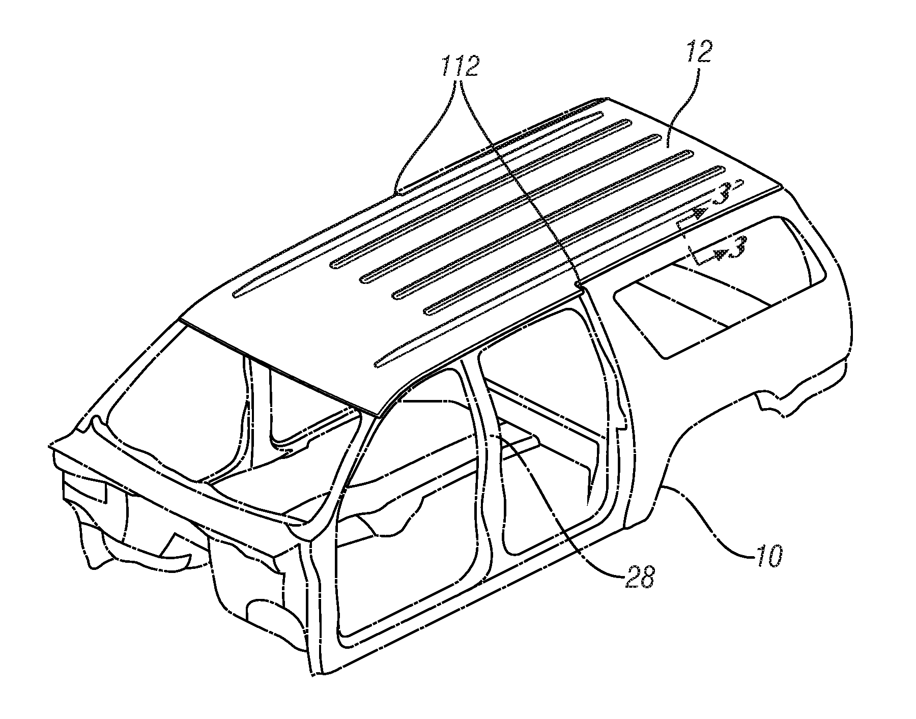
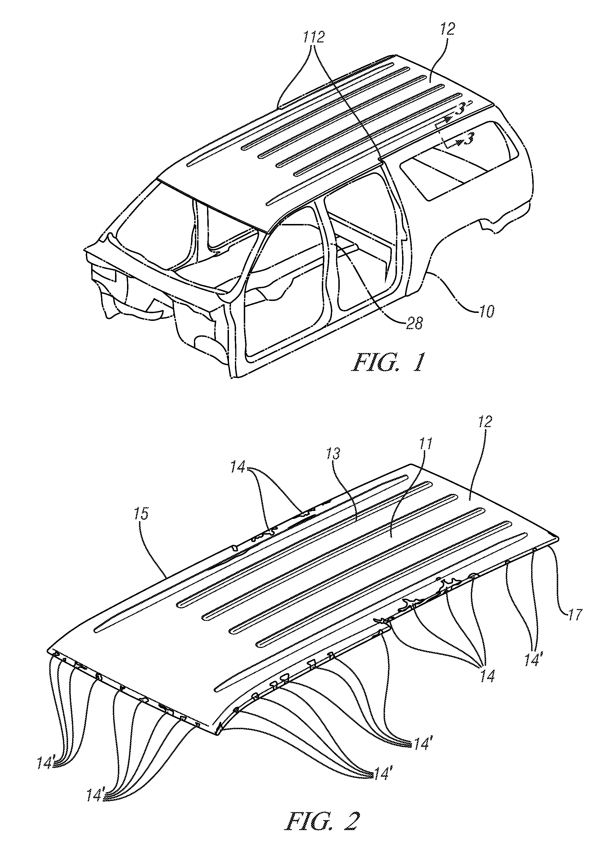
[0032]Increasingly, low-carbon steel, long the material of choice for vehicle body construction, is being displaced by higher strength-to-weight ratio materials such as high strength steels, aluminum alloys and magnesium alloys. This trend is driven by a desire to use materials most effectively, primarily with a goal of reducing vehicle weight for improved fuel economy, and is enabled by the fact that vehicle bodies are permanently-attached assemblages of individual, usually stamped sheet metal, components. Thus, selective material substitution may be achieved on a component by component basis and it is not unusual for attached, abutting components to be formed of different materials. An example of this is the application of an aluminum alloy roof sheet metal panel to a steel, or largely steel, body structure and schematically illustrated in FIG. 1 which shows an aluminum roof stamping 12, positioned on a steel vehicle body structure 10 (shown in ghost) representative of the open in...


PUM

PropertyMeasurementUnit
temperatureaaaaaaaaaa
temperaturesaaaaaaaaaa
stress distributionsaaaaaaaaaa

Abstract

The substitution of aluminum alloy roof panels for the low carbon steel roof panels most commonly used in motor vehicles is an attractive option for vehicle mass reduction. Often, however, the remainder of the vehicle body structure continues to be fabricated of steel. The combination of the aluminum alloy roof attached to the steel body may create compressive stresses in the aluminum roof when the body is subjected to elevated temperatures such as those required to cure or bake the paint applied to the body. These stresses may lead to unacceptable appearance features in the visible segment of the roof. By modifying the roof stamping to introduce a tabbed flange for attachment to the body and / or modifying the generally-vertical wall joining the flange to the roof interior, the stresses may be minimized and relocated to segments of the roof not normally visible.

Description

TECHNICAL FIELD[0001]This invention pertains to the design and shaping of aluminum vehicle roof panels for attachment to supporting steel vehicle body members. More specifically, this invention pertains to the design of such aluminum roof panels to minimize thermal distortion of the roof panels when, for example, a vehicle body is to be repeatedly painted and passed through paint ovens.BACKGROUND OF THE INVENTION[0002]The body structure of modern vehicles is developed by assembling and permanently attaching a plurality of generally stamped parts. In one body construction, variously described as unibody, monocoque, or body-frame-integral (BFI), these stamped parts may cooperate in conveying to the vehicle the desired structural rigidity and strength. Alternatively, the body may be mounted to a separate frame structure.[0003]In many instances the stamped body parts will be assembled from an outer body panel, visible to an outside observer and conveying an aesthetically-pleasing appear...

Claims


Application Information

Patent Timeline
Patent Type & Authority Patents(United States)
IPC IPC(8): B62D25/06
CPCB62D25/06B62D27/02B62D29/008
Inventor CARSLEY, JOHN E.HSU, CHIH-CHENGEDMISON, STEWART
Owner GM GLOBAL TECH OPERATIONS LLC
Why Eureka
Try Eureka