
Positive displacement flowmeter and helical gear

a flowmeter and helical gear technology, applied in the direction of instruments, liquid fuel engines, machines/engines, etc., can solve the problems of inability to realize an idea, disadvantageous low tooth height ratio, and use the oval pitch curve as a reference, etc., to achieve sufficient tooth profile strength, high tooth surface strength of the gear tooth profile, and small specific sliding between the tooth profiles

Inactive Publication Date: 2013-04-23
OVAL CORP
View PDF11 Cites 1 Cited by
  • Summary
  • Abstract
  • Description
  • Claims
  • Application Information

AI Technical Summary

Benefits of technology

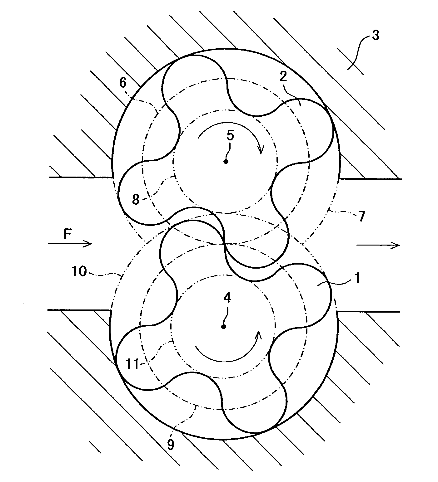
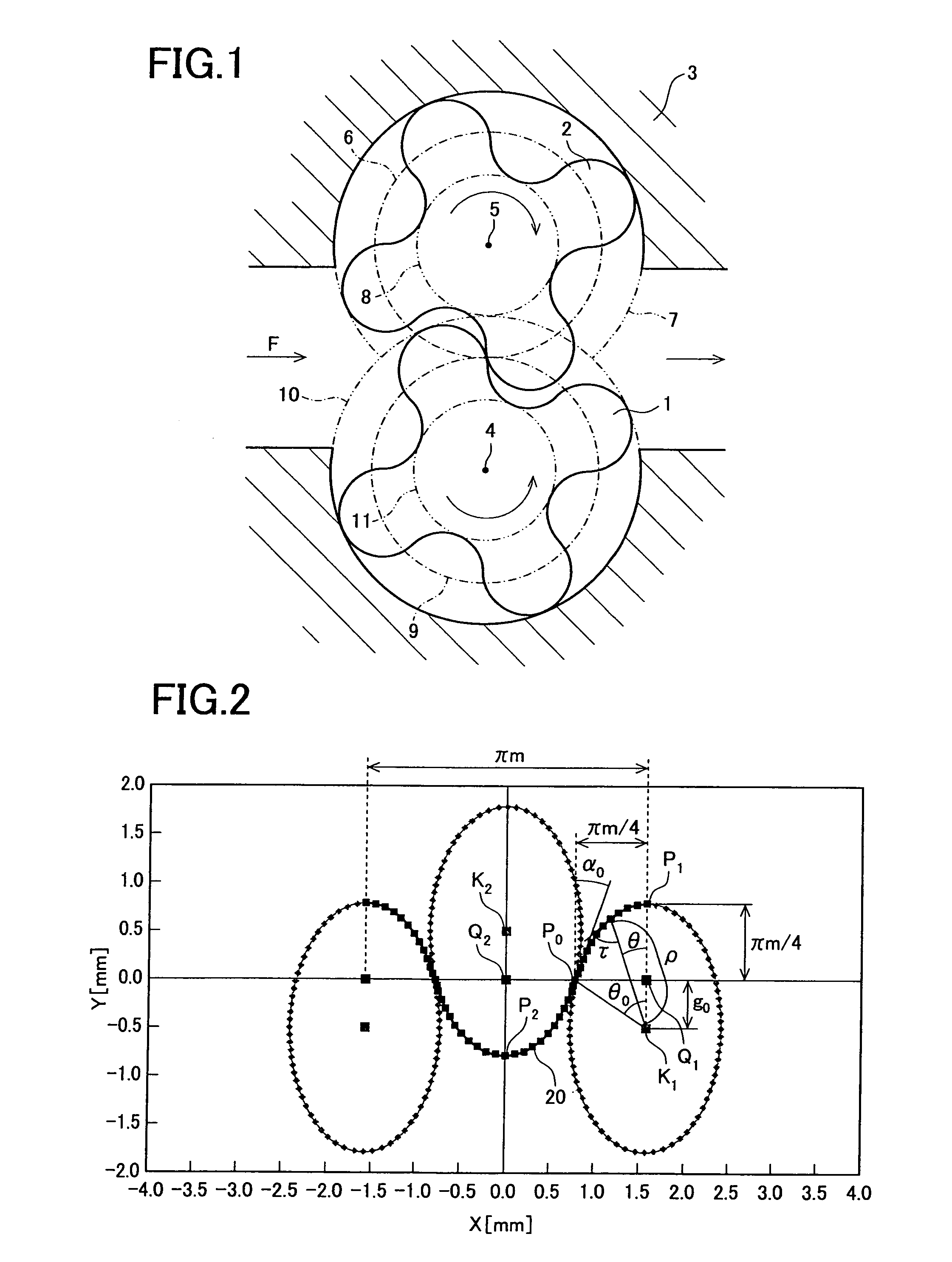
The present invention relates to a method of designing tools or gear cutting processes using helical gears. The invention sets the tooth height ratio of π m / 4, which is the theoretical limit for one-point continuous contact tooth profiles, by incorporating a pair of helical gears that use an oval pitch curve as their reference rack tooth profile. The resulting gear tooth profile is resistant to abrasion as the tooth surfaces are in mesh of a protrusion and a recess, making the tooth surface strength high and the specific sliding between the tooth profiles small. The helical gears are advantageous for designing tools or gear cutting processes as they provide sufficient tooth profile strength for a few teeth and enable the setting of the cutter pressure angle at the pitch point. The invention sets the tooth height ratio to be π m / 4 that is the theoretical limit for one-point continuous contact tooth profiles, which helps in avoiding confinement phenomenon when used in positive displacement flowmeters.

Problems solved by technology

However, the standard tooth height ratio (assuming that the total tooth height is 2 h) for an ordinary involute tooth profile is 1.0 m (for a full tooth height) and, therefore, when a tooth profile is used for a gear of a positive displacement flowmeter or of a gear pump, the one with a low tooth height ratio is disadvantageous due to its contact ratio and its discharge amount.
However, no technical idea as above of employing the oval pitch curve as the reference rack tooth profile has been present for the conventional positive displacement flowmeters, and this technical idea has not been realized so far.

Method used


Image

  • Positive displacement flowmeter and helical gear
  • Positive displacement flowmeter and helical gear
  • Positive displacement flowmeter and helical gear

Examples


first embodiment

[0041]The helical gears 1, 2 according to this embodiment are helical gears that employ an oval pitch curve having two or less leaves as a curve for their reference rack tooth profile. The moving radius of the oval pitch curve is expressed by Equation (1) below.

ρ=a / (1−b cos nθ)  Eq. (1)

In Equation (1), “ρ” is the moving radius that is the distance from the center of the rotation to the oval pitch curve, “a” is a similarity factor, “b” is the degree of flatness, “n” is the number of leaves, and “θ” is the argument (the angle of the moving).

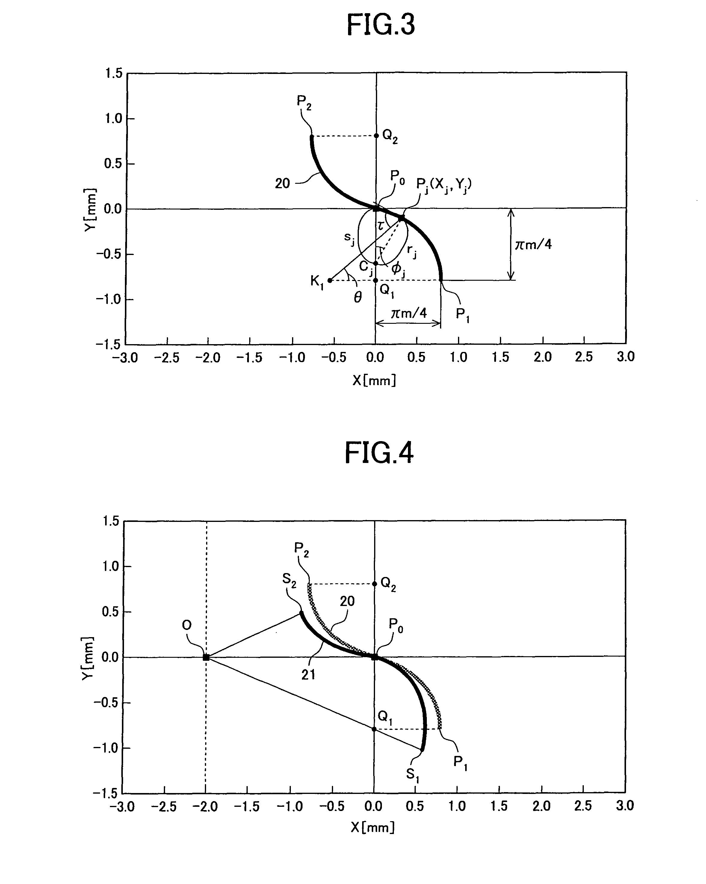
[0042]A locus of the reference rack tooth profile will hereinafter be represented by (Xj, Yj), and the case where a two-leaf oval pitch curve (n=2) is used as the curve for this reference rack tooth profile will be described as a representative example. Here, the pitch circle radius “R”, the number of teeth of the gear “Z”, a tooth profile module “m”, and a ¼ reference pitch “S0” are given below.[0043]The pitch circle radius R=2[0044]The number of ...

second embodiment

[0070]A reference rack tooth profile of this embodiment has the amount of movement of the pole g0=0, and therefore, it is different from the reference rack tooth profile of the first embodiment, the pole of the oval pitch curve is on the pitch line and is configured by providing a straight line section in the vicinity of the pitch point of the reference rack tooth profile.

[0071]Representing the locus of the reference rack tooth profile as (Xj, Yj), the case where a two-leaf oval pitch curve (n=2) is employed as the curve for the reference rack tooth profile will be described as a representative example. Similarly to the first embodiment, the pitch circle radius “R”, the number of teeth of the gear “Z”, a tooth profile module “m”, and a ¼ reference pitch “S0” are given below.[0072]The pitch circle radius R=2[0073]The number of teeth of the gear Z=4[0074]The tooth profile module m=2R / Z=1[0075]The ¼ reference pitch S0=π m / 4=πR / 2Z

[0076]The polar coordinates (ρ, θ) of the two-leaf (n=2) ...


PUM


Abstract

Flowmeter with a pair of helical gears using an oval pitch curve as a reference rack tooth profile. The tooth height ratio of the reference rack tooth profile is π / 4. The reference rack tooth profile is an oval pitch curve of two or less leaves. The moving radius of the oval pitch curve is expressed by ρ=a / (1−b cos nθ), where ρ is a moving radius which is a distance between the center of rotation and the oval pitch curve, “a” is a similarity factor, “b” is a degree of flatness, n (n≦2) is the number of leaves, and θ is an argument. The tooth height ratio is h=a / (1−b)−g0, where g0 is a distance between poles of the oval pitch curve and pitch line, wherein g0=a cos θ0 / (1−b cos nθ0). Values for the similarity factor “a”, degree of flatness “b”, and distance g0 are determined so that the tooth height ratio may be πm / 4.

Description

TECHNICAL FIELD[0001]The present invention relates to a positive displacement flowmeter and a helical gear and more specifically to a pair of helical gears that employ an oval pitch curve as their reference rack tooth profile, and a positive displacement flowmeter that includes the pair of helical gears.BACKGROUND OF THE INVENTION[0002]Conventionally, a helical-gear positive displacement flowmeter is characterized in that the flow meter generates a very small amount of vibrations and noises due to its non-pulsing motion because rotations of its gear are uniform-velocity rotations, its flow is uniform, and its torque is uniform, compared with other gear flow meters. In a gear having relatively a few teeth (the number of teeth Z is 2 to 4) as its gear, the continuous contact tooth profile with which meshing is conducted on the whole surface of the gear tooth profile accompanies no confinement phenomenon, is proper as a tooth profile for a gear of a flow meter, and is variously used in...

Claims


Application Information

Patent Timeline
Patent Type & Authority Patents(United States)
IPC IPC(8): F01C21/00F03C2/00F03C4/00
CPCG01F3/10
Inventor ONO, SEIGOUCHIDA, KATSUICHI
Owner OVAL CORP
Learn More