Cartridge type heater

a heater and cartridge technology, applied in the field of cartridge heaters, can solve the problems of cumbersome and expensive filling of granular insulating materials, difficult filling, and high labor intensity, and achieve the effects of low labor intensity, minimal amount of material, and low cos

Active Publication Date: 2013-04-23
TUERK & HILLINGER
View PDF17 Cites 20 Cited by
  • Summary
  • Abstract
  • Description
  • Claims
  • Application Information

AI Technical Summary

Benefits of technology

[0007]The basic object of the present invention is to provide a cartridge type heater of the type mentioned in the introduction which can be manufactured at a low cost with minimal labor and with the use of a minimal amount of material.
[0009]Due to the arrangement according to the present invention and to the fact that a dimensionally stable carrier wall consisting of insulating material is provided with at least one coil holder, which maintains the hot wire coils tensioned along the carrier wall during both the introduction into the metal jacket and during the subsequent filling in of the insulating granular material, the manufacture of such cartridge type heaters becomes substantially simpler and cheaper. Spacers, which keep the hot wire coils away from the metal jacket, may even be dispensed with in case of short metal jackets that do not have a minimal thickness (below 3 mm in diameter). A substantially smaller number of spacers is sufficient than in conventional cartridge type heaters of the type of this class in case of very long cartridge type heaters of 1.5 m in length and longer. In addition, the ends of the hot wire coils may be provided with the terminal elements already before they are introduced into the metal jacket and fixed in their final, functionally correct position to the coil holder or coil holders in a very simple manner, the tensile stress generated also facilitating this operation.
[0012]Another simple possibility of insulating the coil section led around this lower end edge against the bottom of the metal jacket and of keeping it away from this is to provide a grommet or a spacer ring.
[0015]The embodiment wherein a second coil holder is attached to an end section of the carrier wall and the end section is located away from the terminal and terminal connectors are provided at that end also shows a very advantageous possibility of accommodating safety switching elements against thermal overload in the area of the closed end section of the metal jacket.
[0016]It is advantageous for cartridge type heaters that have a greater length to provide spacers. The risk of the hot wire coils coming into contact with the metal jacket can be avoided by these spacers in case of greater overall lengths as well.
[0017]The insulation and safety against dielectric breakdown of the hot wire coils against the metal jacket can be considerably increased with the other embodiments wherein a single-layer or multilayer insulating film is placed on the inner surface of the metal jacket and within the insulating film the hot wire coil being embedded in the granulated insulating material. The insulating film may advantageously consist of polyamide.

Problems solved by technology

This working method is very time-consuming and hence cost-intensive.
The filling in of the granular insulating material is cumbersome and expensive in this cartridge type heater as well.
No support elements, which would ensure that the windings of the heating coil do not come into contact with the tube wall when the insulating granular material is being filled in, are provided for the hot wire coil within the metal tube in these prior-art cartridge type heaters.
This makes it difficult to fill in the granular material and causes high manufacturing costs.

Method used


Image

  • Cartridge type heater
  • Cartridge type heater
  • Cartridge type heater

Examples


Embodiment Construction

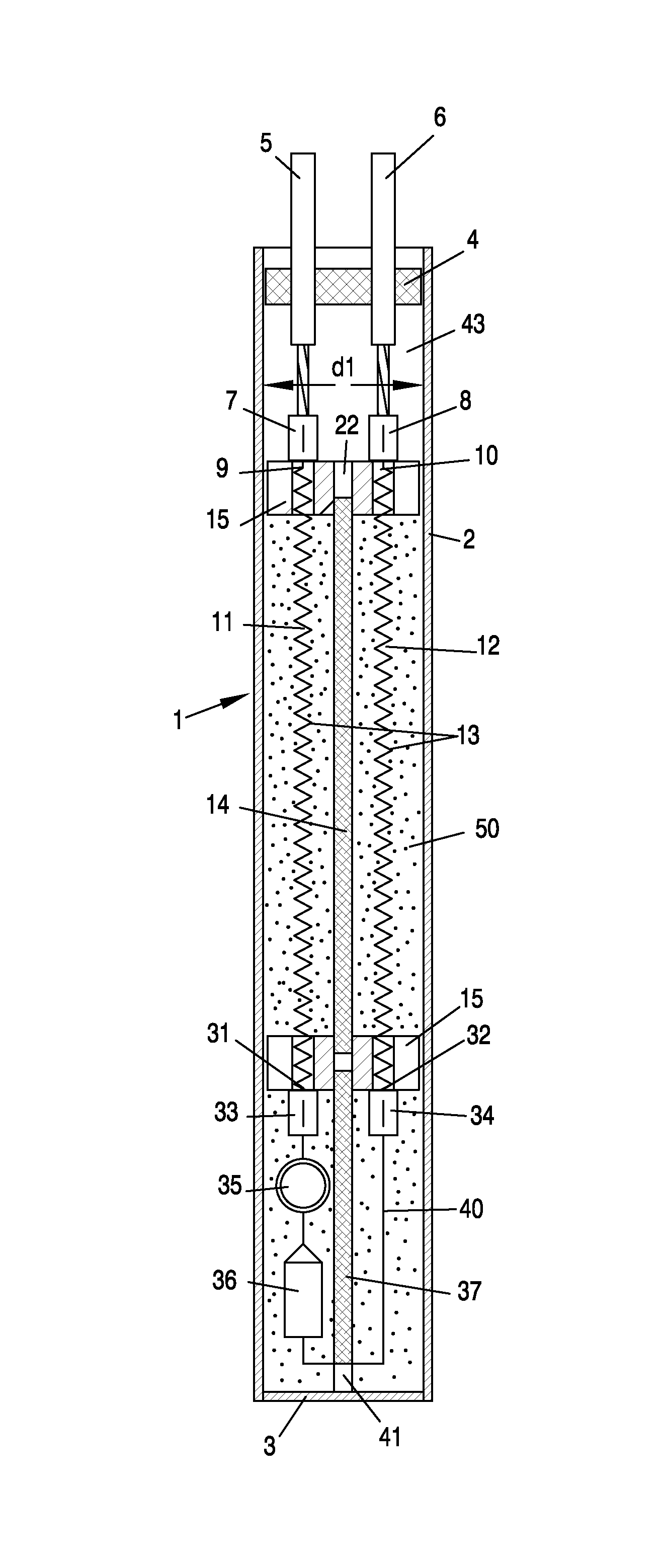
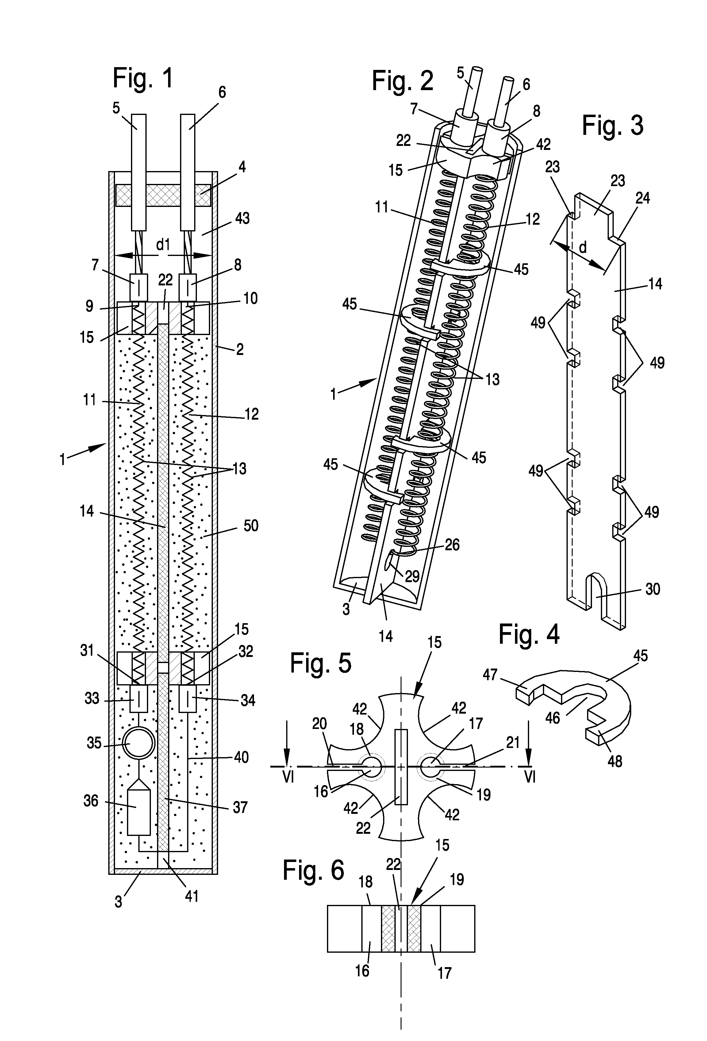
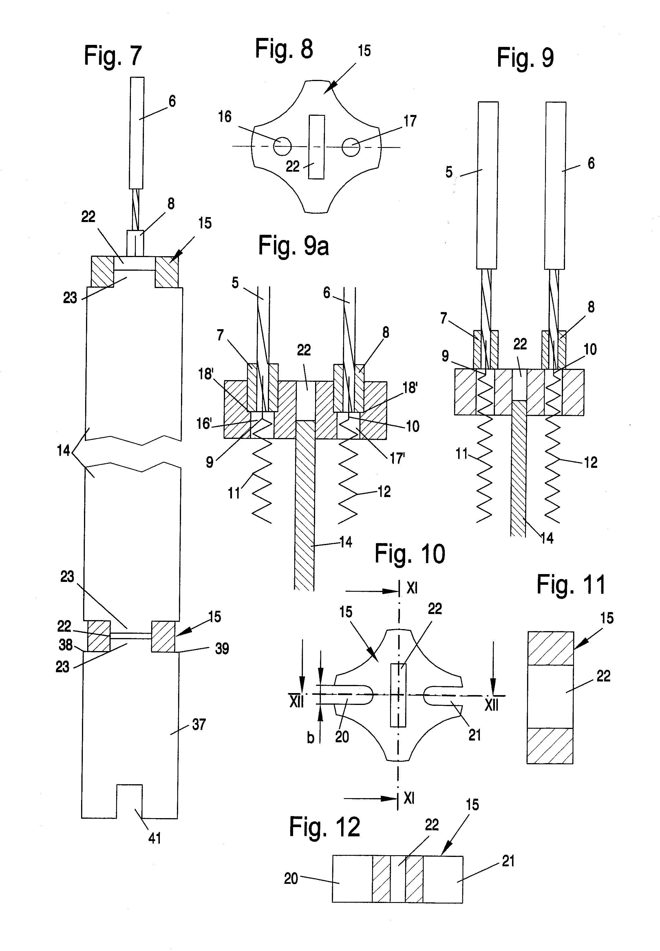
[0046]Referring to the drawings in particular, the respective cartridge heaters 1 and 1 / 1 shown in FIGS. 1 and 2 with wire coil 13 and carrier wall 14 have a cylindrical metal jacket 2 each, which is provided with a fixed bottom 3 and whose upper open end may be closed, as in FIG. 1, by a closing disk 4. Metal jacket 2 preferably consists of copper or stainless steel.

[0047]The closing disk 4 consists of an insulating material and is provided with passage holes for two terminal strands 5 and 6. The hot wire ends 9 and 10 of a hot wire coil 13 comprising two coil strands 11 and 12 are connected in an electrically contacting and mechanically tension-proof manner to these terminal strands 5, 6 provided with insulating jackets by means of respective terminal connectors 7 and 8.

[0048]The two coil strands 11 and 12 extend along the two flat sides of the carrier wall 14, which is arranged centrally in the metal jacket 2 and which acts as a carrier for the two coil strands 11, 12 of the hot ...


PUM


Abstract

A cartridge type heater is provided with at least one hot wire coil (13), which has two coreless coil strands (11, 12), which extend in an insulating material (50) along the two sides of a carrier wall (14). The heater includes an insulating material that is coordinated with the internal diameter of a metal jacket (2). The hot wire ends (9, 10) are provided with terminals projecting from the same end of the metal jacket (2). The hot wire coils (11, 12) are electrically connected to one another in the area of an end edge of the carrier wall (14). This edge is located in the closed end area of the metal jacket (2) and the coils are guided by spacers (45) distributed at the longitudinal edges of the carrier wall (14). At least the terminal-side end of the dimensionally stable carrier wall (14) is provided with an attached coil holder (15, 15 / 1), to which the hot wire ends (9, 10) are fastened under tensile stress. This keeps the windings of the hot wire coil (13) spaced apart from each other. At least one filling opening (42) is provided for the granulated insulating material (50).

Description

CROSS REFERENCE TO RELATED APPLICATIONS[0001]This application claims the benefit of priority under 35 U.S.C. §119 of German Patent Application DE 20 2008 016 439.7 filed Dec. 11, 2008, the entire contents of which are incorporated herein by reference.FIELD OF THE INVENTION[0002]The present invention pertains to a cartridge type heater (cartridge heater) with at least one hot wire coil, which has at least two, preferably coreless coil strands, which extend along the two sides of a carrier wall consisting of insulating material, whose width is coordinated with the internal diameter of a metal jacket and are embedded in the metal jacket in a granulated insulating material, wherein the ends of the hot wire are provided with respective terminals projecting each from the same end of the metal jacket, and wherein the hot wire coils are electrically connected to one another in the area of an end edge facing the closed end of the metal jacket, which said end is away from the terminal, and wh...

Claims


Application Information

Patent Timeline
Patent Type & Authority Patents(United States)
IPC IPC(8): H05B3/02
CPCH05B3/48
Inventor SCHLIPF, ANDREAS
Owner TUERK & HILLINGER
Why Eureka
Try Eureka