
Forward error correction (FEC) auto negotiation for an optical transport network (OTN)

a technology of forward error correction and auto negotiation, applied in the field of communication systems, can solve the problems of communication devices, exponentially increasing complexity, and relatively high retransmission costs

Active Publication Date: 2013-04-30
MACOM CONNECTIVITY SOLUTIONS LLC
View PDF15 Cites 14 Cited by
  • Summary
  • Abstract
  • Description
  • Claims
  • Application Information

AI Technical Summary

Benefits of technology

The patent text describes a system and method that allows Optical Transport Network (OTN) equipment to automatically negotiate a mutually beneficial forward error correction (FEC) type. This negotiation process takes into account actual bit errors and allows different vendors or same vendors with multiple FEC capabilities to interoperate automatically. The mechanism is flexible, allowing selection of a preferred FEC type and either in-band or out-band data streams can be used as the carrier to communicate the required information. The mechanism is automated, eliminating the need for human operators to manually set one of the available FEC types in local and remote OTN equipment.

Problems solved by technology

FEC is therefore applied in situations where retransmissions are relatively costly, or impossible such as when broadcasting to multiple receivers.
Viterbi decoding allows asymptotically optimal decoding efficiency with increasing constraint length of the convolutional code, but at the expense of exponentially increasing complexity.
Thus, communicating devices, if made by different vendors for example, may not necessarily be able to communicate using a common FEC algorithm.
However, this method does not provide a means for the transmitter and receiver to negotiate on the subject of a common FEC algorithm.
However, no means is described for negotiating between a transmitter and receiver, to select a mutually beneficial FEC algorithm.

Method used


Image

  • Forward error correction (FEC) auto negotiation for an optical transport network (OTN)
  • Forward error correction (FEC) auto negotiation for an optical transport network (OTN)
  • Forward error correction (FEC) auto negotiation for an optical transport network (OTN)

Examples


Embodiment Construction

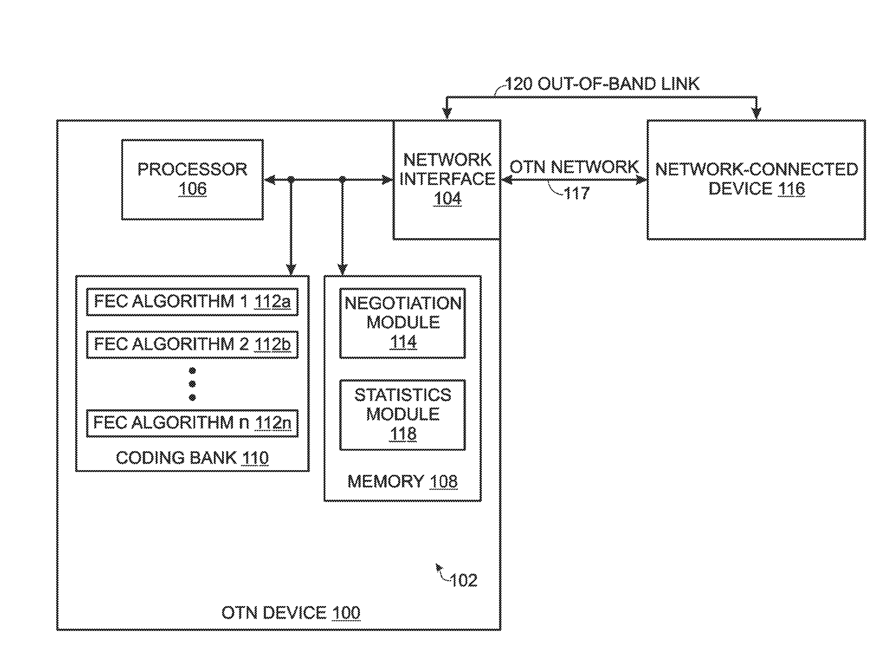
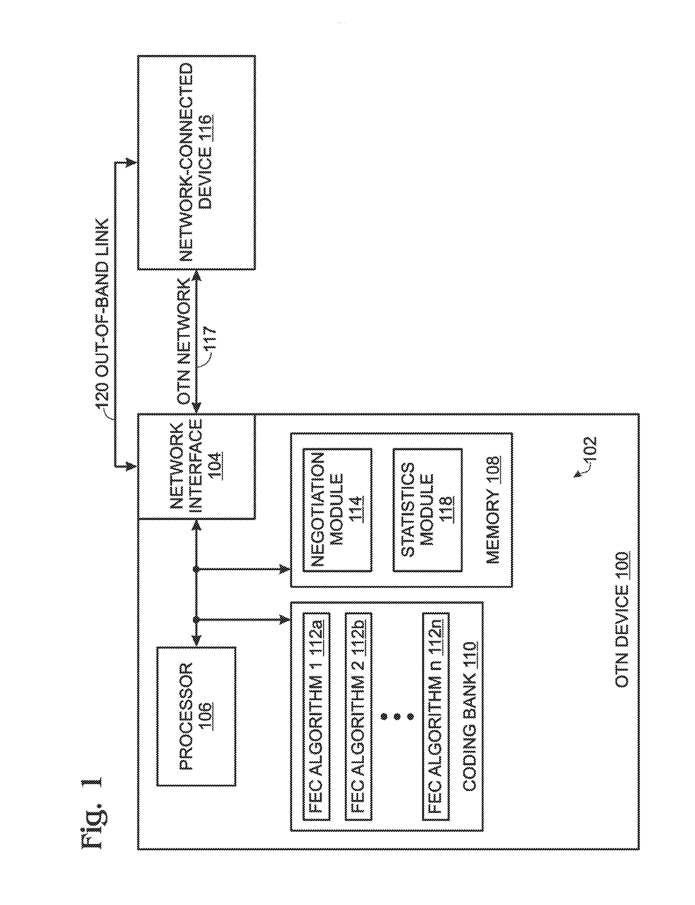
[0045]FIG. 1 is a schematic block diagram of an Optical Transport Network (OTN) communication device 100 using a plurality of forward error correction (FEC) algorithms, with a system for auto negotiating an FEC algorithm between network-connected devices. The system 102 comprises a network interface 104, a processor 106, and a local tangible memory 108.

[0046]As used in this application, the terms “component,”“module,”“system,” and the like may be intended to refer to an automated computing system entity, such as hardware, firmware, a combination of hardware and software, software, software stored on a computer-readable medium, or software in execution. For example, a component may be, but is not limited to being, a process running on a processor, a processor, an object, an executable, a thread of execution, a program, and / or a computer. By way of illustration, both an application running on a computing device and the computing device can be a component. One or more components can re...


PUM


Abstract

In an Optical Transport Network communication device using a plurality of forward error correction (FEC) algorithms, a method is provided for auto negotiating an FEC algorithm between network-connected devices. The first device sends an FEC auto negotiation (AN) request message to a second device. If the first device receives the FEC AN response from the second device, the first device selects the FEC algorithm suggested in the FEC AN response. In the event that the first device is unable to negotiate a mutually agreed upon FEC algorithm with the second device, the first device enters a trial-and-error mode, beginning with a first FEC algorithm. The first device iteratively cycles through each of the plurality of n FEC algorithms, and measures error statistics associated with the nth FEC algorithms. The first device compares the n sets of error statistics and selects an FEC algorithm associated with the minimum number of errors.

Description

BACKGROUND OF THE INVENTION[0001]1. Field of the Invention[0002]This invention generally relates to communication systems and, more particularly, to a system and method for negotiating a forward error correction (FEC) algorithm where at least one link partner is optionally capable of transceiving messages with more than one FEC algorithm.[0003]2. Description of the Related Art[0004]As noted in Wikipedia, forward error correction (FEC) or channel coding is a system of error control for data transmission, whereby the sender adds systematically generated redundant data to its messages, also known as an error-correcting code. A carefully designed redundancy permits the receiver to detect and correct a limited number of errors occurring anywhere in the message without the need to ask the sender for additional data. FEC gives the receiver an ability to correct errors without needing a reverse channel to request retransmission of data, but this advantage is at the cost of a fixed higher fo...

Claims


Application Information

Patent Timeline
Patent Type & Authority Patents(United States)
IPC IPC(8): H03M13/00H04L1/18
CPCH03M13/353H03M13/6306H04L1/0035H04L1/0039H03M13/1102H04J2203/0057H03M13/132H03M13/136H03M13/1505H03M13/1515H03M13/152H03M13/19H03M13/23H03M13/2957H03M13/3761H03M13/51H04L1/0009H03M13/1194
Inventor WU, CHAOPING
Owner MACOM CONNECTIVITY SOLUTIONS LLC
Learn More