Oxygen separation module and apparatus

a technology of oxygen separator and oxygen tank, which is applied in the direction of refrigeration machines, electrodialysis, refrigeration components, etc., can solve the problem of electricly driven oxygen separator being withdrawn from servi

Active Publication Date: 2013-05-07
PRAXAIR TECH INC
View PDF17 Cites 24 Cited by
  • Summary
  • Abstract
  • Description
  • Claims
  • Application Information

AI Technical Summary

Benefits of technology

[0015]The tubular membrane elements are arranged in a bundle and held in place by two opposed end insulation members located adjacent to the opposed ends of the tubular membrane elements. The bundle is positioned within the enclosure and with the end insulation members situated within the openings of the end walls and the opposed ends of the tubular membrane elements and the end seals thereof projecting outwardly from the end insulation members and into the two inlet regions. At least one manifold is connected to the tubular membrane elements and configured to collect the oxygen produced by the tubular membrane elements. Inlets are located within the two end insulation members for passage of two oxygen containing feed streams from the inlet regions to the heated interior region and two blowers connected to the two inlet regions to circulate the oxygen containing feed stream into the inlet region and past the end seals to cool the end seals and then, through the inlets, thereby to contact the membrane elements inside the heated enclosure and to discharge a heated retentate from the heated enclosure that is formed by separation of the oxygen from the oxygen containing feed stream. The cooling of the end seals help to prevent failure of the electrically driven oxygen separator in the first instance.

Problems solved by technology

While the oxygen will of course be delivered at a lower rate after such a failure, unlike electrically driven oxygen separators of the prior art, the failure of one or more elements will not necessarily result in the electrically driven oxygen separator being withdrawn from service.

Method used


Image

  • Oxygen separation module and apparatus
  • Oxygen separation module and apparatus
  • Oxygen separation module and apparatus

Examples


Embodiment Construction

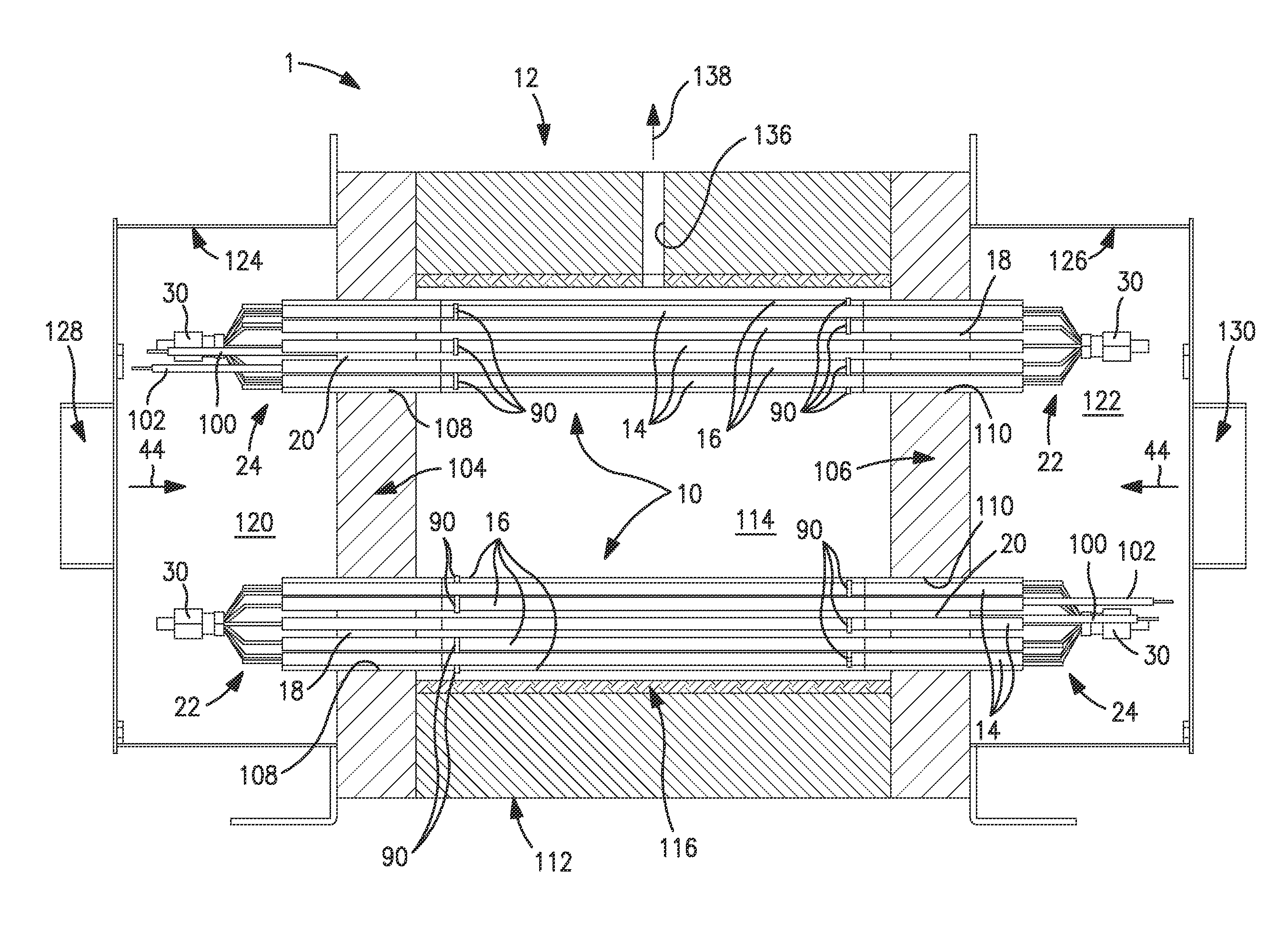
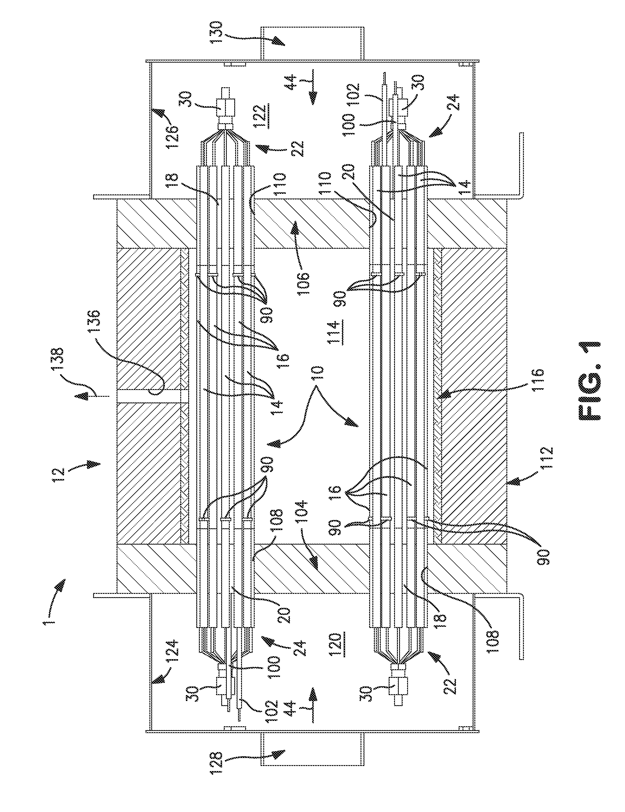
[0026]With reference to FIG. 1, an electrically driven oxygen separator 1 of the present invention is illustrated that has two modules 10 housed within an enclosure 12. It is understood that there could be more or fewer modules 10 depending upon the application of an oxygen separation in accordance with the present invention.

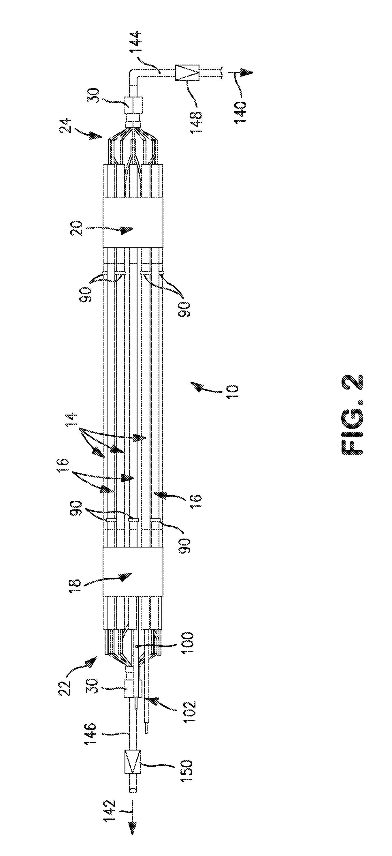
[0027]With reference to FIG. 2, each of the module 10 are formed by a bundle of tubular membrane elements that are divided into a first portion of the tubular membrane elements 14 and a second portion of the tubular membrane elements 16. The first and second portions of the tubular membrane elements are held in position by end insulation members 18 and 20 that are fabricated from high purity alumina fiber. The tubular membrane elements for exemplary purposes can have an outer diameter of about 6.35 mm., a total wall thickness of about 0.5 mm. and a length of about 55 cm. The oxygen that is separated by such first and second portions of the tubular membrane eleme...


PUM

PropertyMeasurementUnit
thicknessaaaaaaaaaa
outer diameteraaaaaaaaaa
lengthaaaaaaaaaa

Abstract

A module and an apparatus incorporating such module utilizing a plurality of tubular membrane elements, each configured to separate oxygen from an oxygen containing feed stream when an electric potential difference is applied to induce oxygen ion transport in an electrolyte thereof. The tubular membrane elements can be arranged in a bundle that is held in place by end insulating members. The insulating members can be positioned within opposed openings of end walls of a heated enclosure and can incorporate bores to allow an oxygen containing feed stream to flow past exposed ends of the tubular membrane elements for cooling the end seals of such elements. Further, first and second manifolds can be provided in a module in accordance with the present invention to collect separated oxygen from two separate portions of the tubular membrane elements.

Description

FIELD OF THE INVENTION[0001]The present invention relates to an oxygen separation module and apparatus that incorporates a plurality of tubular membrane elements, each configured to separate oxygen from an oxygen containing feed stream when an electric potential difference is applied to produce oxygen ion transport through an electrolyte of the tubular membrane elements. More particularly, the present invention relates to such an oxygen separation module and apparatus in which manifolds to collect the separated oxygen are positioned at opposite ends of the tubular membrane elements and are connected to the tubular membrane elements such that a portion of the tubular membrane elements are connected to one of the manifolds and another portion of the tubular membrane elements are connected to the other of the manifolds.BACKGROUND OF THE INVENTION[0002]Electrically driven oxygen separators are used to separate oxygen from oxygen containing feed, for example, air. Additionally, such devi...

Claims


Application Information

Patent Timeline
Patent Type & Authority Patents(United States)
IPC IPC(8): B01D53/22
CPCB01D53/326B01D63/06C01B13/0251C01B13/0255B01D53/228B01D53/227B01D2256/12B01D2311/06B01D2313/04B01D2313/12B01D2313/345B01D2319/04B01D63/069B01D2313/042
Inventor CHRISTIE, GERVASE MAXWELLREED, DAVID M.NEFF, JERRINE L.SELOVER, ARTHUR C.
Owner PRAXAIR TECH INC
Why Eureka
Try Eureka