

Integrated gas discharge lamp and ignition transformer for an integrated gas discharge lamp
a technology of integrated gas discharge and ignition transformer, which is applied in the direction of magnetic discharge control, transit-tube circuit elements, cathode-ray/electron beam tube circuit elements, etc., can solve the problems of complex transformer production, coil space available, and high cost, so as to increase the mechanical stability and the strength of electrical insulation, improve the current flow, and simple and secure manner
Inactive Publication Date: 2013-05-07
OSRAM GMBH
View PDF26 Cites 11 Cited by
- Summary
- Abstract
- Description
- Claims
- Application Information
AI Technical Summary
Benefits of technology
The present invention is directed to an ignition transformer for a gas discharge lamp. The transformer has a ferrite core and at least one primary and one secondary winding. The secondary winding is made of a metal strip that is placed on the ferrite core and the end of the winding carrying the high voltage is on the inside. The ferrite core is designed like a film reel and the secondary winding is wound onto it like a film. This design makes the transformer easy and inexpensive to produce. The ratio of diameter to height of the ferrite core is preferably between 1 and 9, which makes the transformer compact and efficient.
Problems solved by technology
However, this is involved and expensive since there are no constructional measures for insulating the voltage, but the insulation of the wire must accomplish precisely this.
However, this transformer is complex to produce since the secondary winding cannot be wound on the ferrite, but instead has to be wound on a mandrel and can only be inserted into the cup-core-shaped ferrite as a finished coil.
Owing to the manufacturing tolerances, the coil space available in this instance is not well utilized and the coupling also is not optimal.
Method used
View moreImage
Smart ImageViewing Examples

Examples
first embodiment
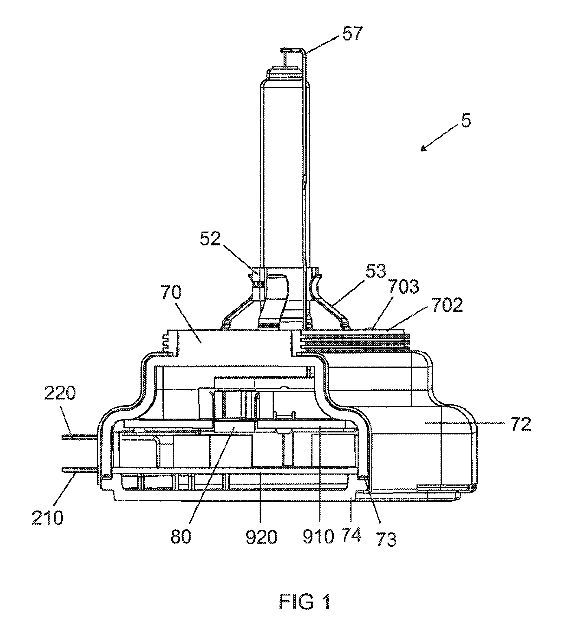
[0022]FIG. 1 shows a sectional view of an integrated gas discharge lamp according to the invention;
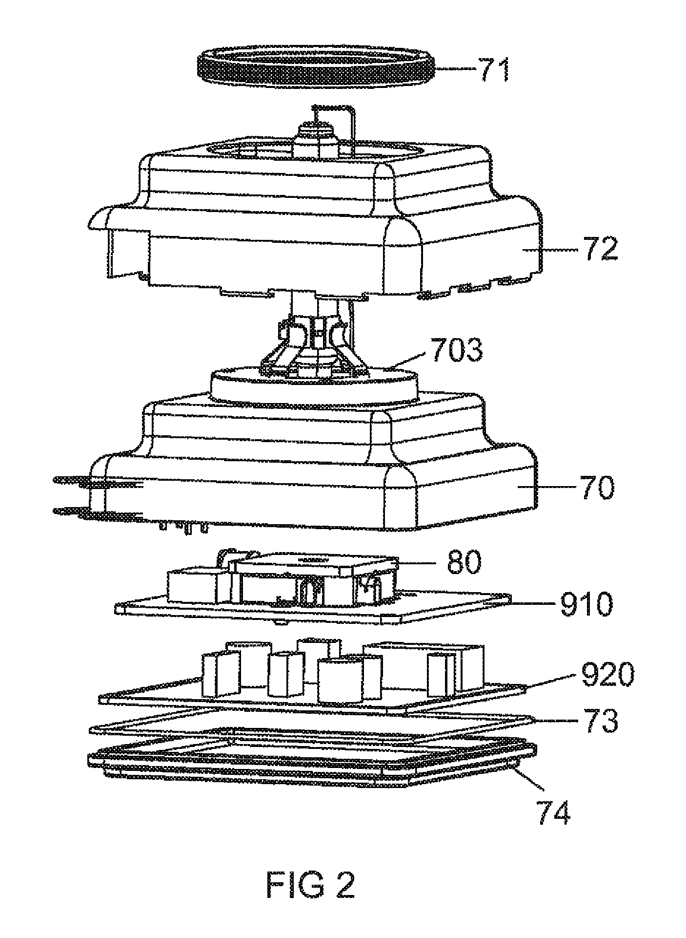
[0023]FIG. 2 shows an exploded view of the first embodiment of the mechanical components of the integrated gas discharge lamp;
second embodiment
[0024]FIG. 3 shows a sectional view of an integrated gas discharge lamp according to the invention;
[0025]FIG. 4 shows a perspective view of a second embodiment of an integrated gas discharge lamp according to the invention;
[0026]FIG. 5 shows a view of the headlamp / gas discharge lamp interface;
[0027]FIG. 6 shows a detail of the electrical contact;
[0028]FIG. 7 shows a detail of the mechanical contact;
third embodiment
[0029]FIG. 8 shows a sectional view of the integrated gas discharge lamp;
Login to View More PUM
| Property | Measurement | Unit |
|---|---|---|
| diameter | aaaaa | aaaaa |
| height | aaaaa | aaaaa |
| voltage | aaaaa | aaaaa |
Abstract
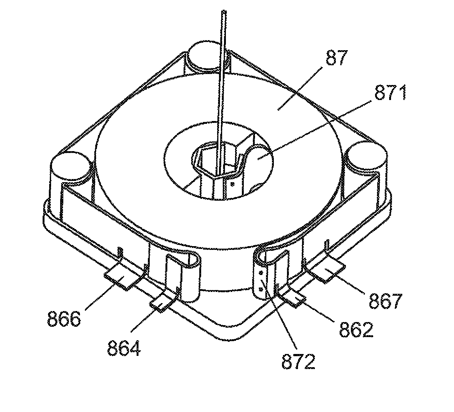
An ignition transformer (80) for generating an ignition voltage for a high-pressure gas discharge lamp (5) which has a high-pressure gas discharge lamp burner (50), comprising a ferrite core (81) and at least one primary winding (86) and at least one secondary winding (87), the at least one secondary winding (87) being formed from an insulated metal strip that is disposed on the ferrite core (81) in such a way that the end of the at least one secondary winding (87) that carries the high-voltage is disposed on the inside, wherein the ferrite core has the form of a film reel, and the secondary winding (87) is wound onto the ferrite core like a film.
Description
RELATED APPLICATIONS[0001]This is a U.S. National Stage of application No. PCT / EP2009 / 065358, filed on Nov. 18, 2008.[0002]This application claims the priority of German application no. 10 2008 059 545.4 filed Nov. 28, 2008 and 10 2008 059 561.6 filed Nov. 28, 2008, the entire content of both of which are hereby incorporated by reference.FIELD OF THE INVENTION[0003]The invention relates to an integrated gas discharge lamp and an ignition transformer for an integrated gas discharge lamp for generating an ignition voltage, comprising a ferrite core and at least one primary winding and at least one secondary winding, wherein the at least one secondary winding is formed from an insulated metal strip that is disposed on the ferrite core in such a way that the end of the at least one secondary winding carrying the high voltage is disposed on the inside.BACKGROUND OF THE INVENTION[0004]DE 199 13 942 C1 discloses an integrated gas discharge lamp which comprises an integrated ignition device...
Claims
Login to View More Application Information
Patent Timeline
 Patent Type & AuthorityPatents(United States)
IPC IPC(8): H01F17/04H01F27/29H01J7/44H01J1/50
CPCH01F27/2847H01F38/12H05B41/2881H05B41/2925H05B41/2928H01F27/29H01F27/327Y02B20/204H01F2027/2857Y02B20/00
InventorROHL, MANFREDSIESSEGGER, BERNHARD
OwnerOSRAM GMBH