
Lens pad, lens pad manufacturing method, lens manufacturing method, and adhesive member

a technology of lens pads and adhesive parts, which is applied in the direction of manufacturing tools, paper/cardboard containers, paper/cardboard articles, etc., can solve the problems of easy peeling, affecting the adhesion of adhesive tapes, and prone to shift of the attachment portion of adhesive tapes, so as to achieve satisfactory shaping and low coefficient of surface friction

Active Publication Date: 2013-05-14
HOYA CORP +1
View PDF12 Cites 0 Cited by
  • Summary
  • Abstract
  • Description
  • Claims
  • Application Information

AI Technical Summary

Benefits of technology

The present invention aims to address problems with shaping water-repellent lenses with low coefficients of surface friction that may have axial deviation. The invention provides a lens pad that can satisfactorily shape such lenses without any attachment issues. Additionally, the invention also provides an adhesive member that can maintain a good attachment state even when subjected to a shearing force.

Problems solved by technology

However, since a water-repellent surface inhibits adhesion of other substances, it naturally inhibits adhesion of adhesive tape as well.
In other words, even when adhesive tape is attached onto a water-repellent surface, it readily peels off.
In addition, when a force acts on the adhesive surface of the adhesive tape in the direction of shearing, the adhesion of the adhesive tape on the water-repellent surface is readily released, and the attachment portion of the adhesive tape is consequently prone to shift.
Furthermore, in this step, a heavy load is imposed on the adhesive interface.
However, it is difficult to stably attach the above-mentioned pad onto a water-repellent lens.
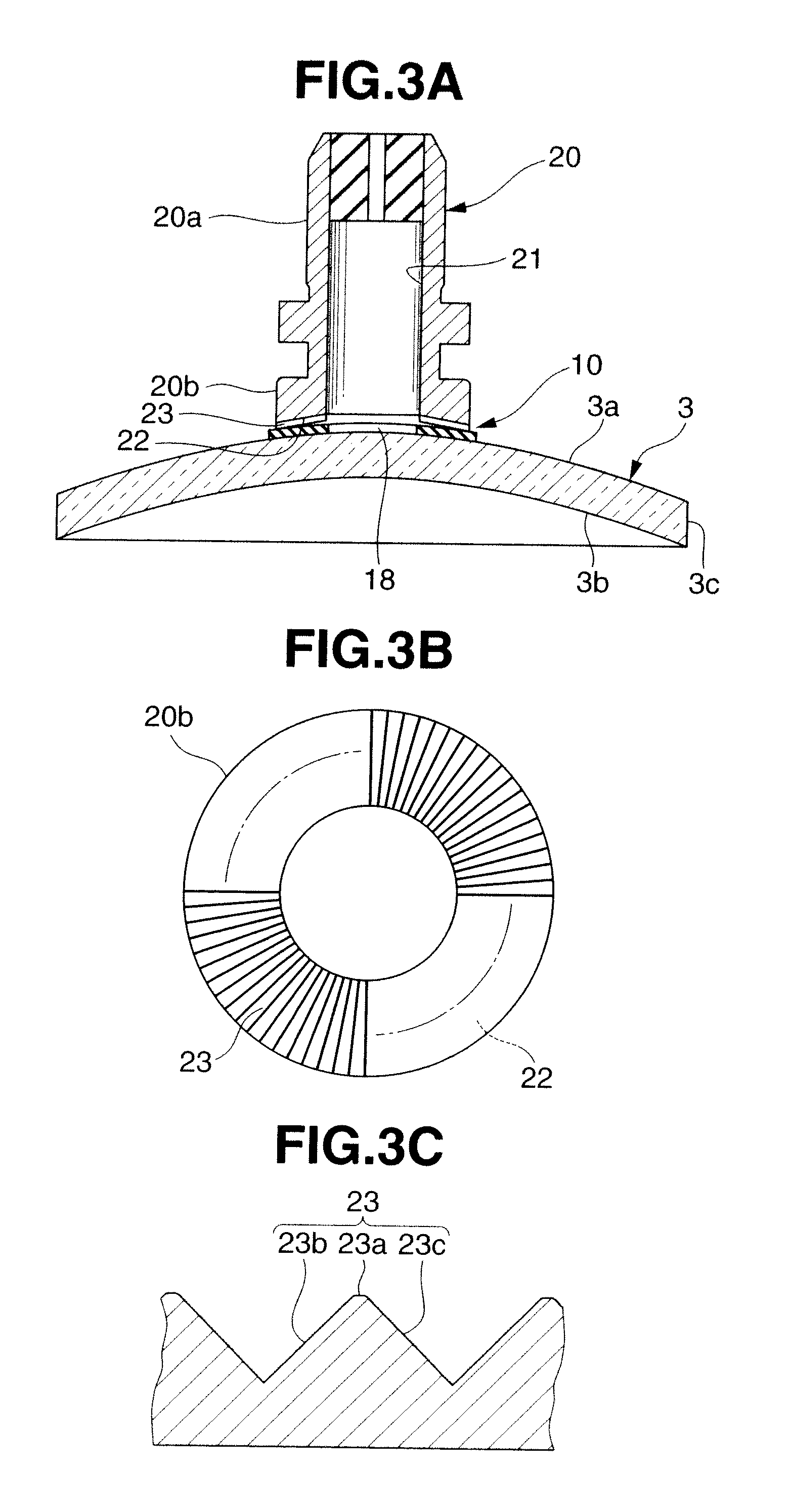
Furthermore, when a water-repellent lens is shaped into a specific edge shape using a rotary edging tool, a shearing force is inflicted on the interface between the adhesive surface of the pad and the lens surface.
Under such demanding conditions, the attachment position of the pad is prone to shift.
However, it is difficult to obtain an expected effect even by specifying the adhesive strength by its adhesive force acting upon its peel-off because the sheet itself is pressed by the lens fixing jig at the time of lens shaping.
However, even the use of the tape described in patent reference 5 may result in an axial deviation when the adhesive surface floats due to entrance of water or air into the opening during edging.
This makes it difficult to perfectly prevent any axial deviation phenomenon of the lens 3.
This makes it impossible to maintain a good adhesion state in the adhesive region.
When the pad is attached onto a water-repellent lens surface, the use of tape with a specification including a minute opening makes it impossible to maintain a tight contact state between the tape and the lens surface, resulting in an axial deviation phenomenon.

Method used


Image

  • Lens pad, lens pad manufacturing method, lens manufacturing method, and adhesive member
  • Lens pad, lens pad manufacturing method, lens manufacturing method, and adhesive member
  • Lens pad, lens pad manufacturing method, lens manufacturing method, and adhesive member

Examples


example 1

[0058]In this Example, pads respectively including release sheets A, B, C, D, E, F, and G with different surface roughnesses were used to compare and examine the differences in axial deviation performance attributed to the roughnesses of the lens-side adhesive surfaces of the respective release sheets.

[0059]The features of the respective release sheets and the roughnesses of their surfaces which come into tight contact with a lens-side adhesive layer will be explained first.

[0060]The release sheet A is a transparent sheet made of polyethylene terephthalate, has an arithmetic average roughness of 0.06 μm, and exhibits a roughness curve with a maximum cross-sectional height of 0.66 μm.

[0061]The release sheet B is a transparent sheet made of polyethylene terephthalate, has an arithmetic average roughness of 0.02 μm, and exhibits a roughness curve with a maximum cross-sectional height of 0.184 μm.

[0062]The release sheet C is a paper sheet and its surface which comes into tight contact w...

example 2

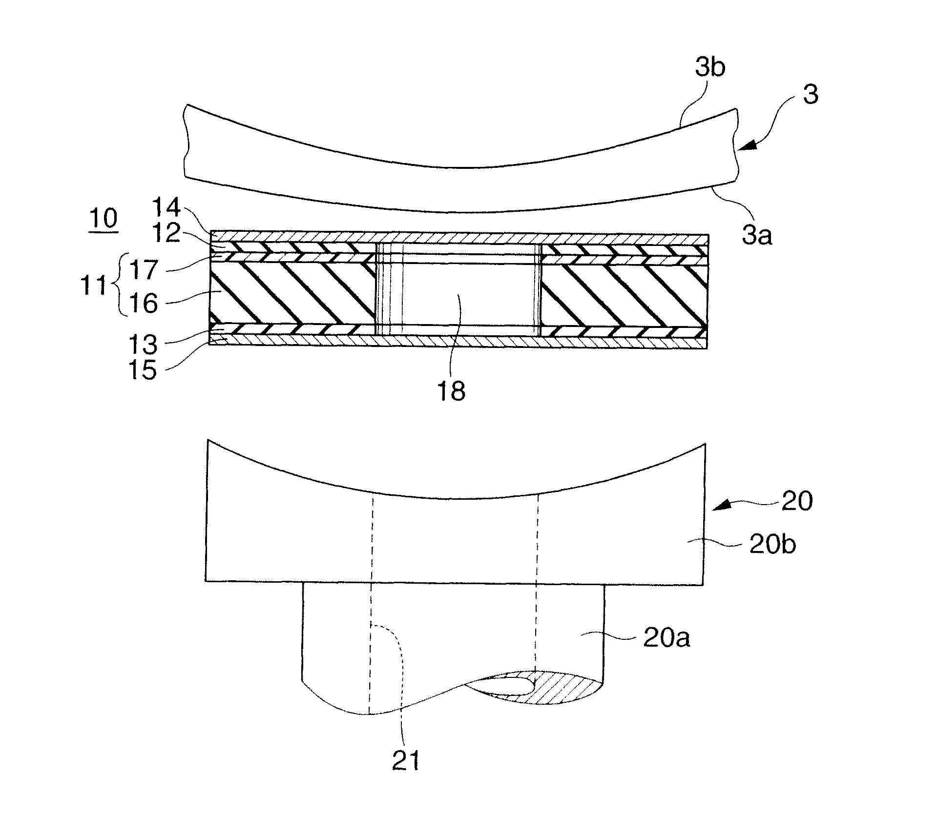
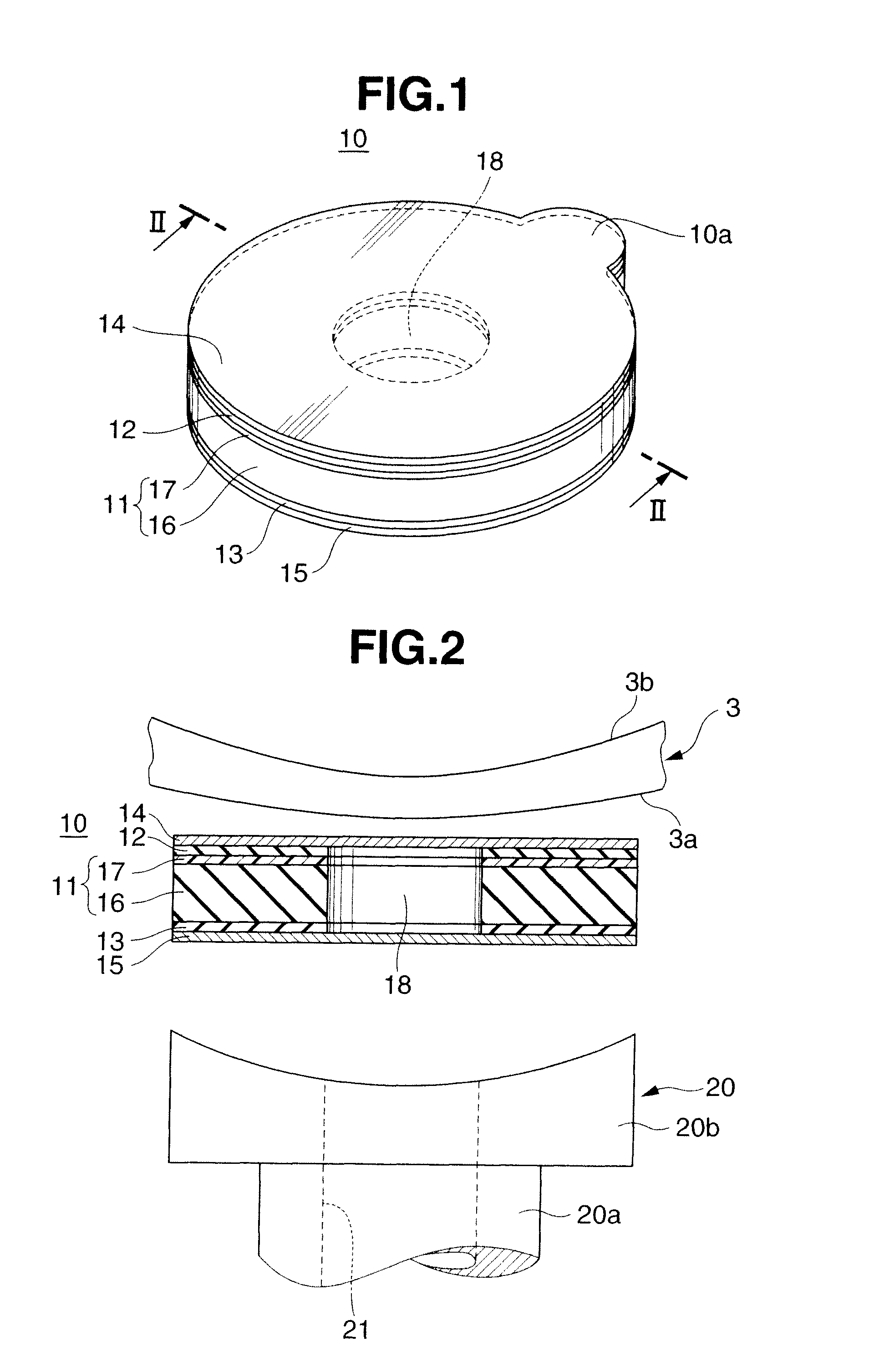
[0076]Next, some samples of lens pads 10 which include cushion layers 16 with different thicknesses, blanks with different densities, and adhesive layers 12 and 13 with different adhesive forces and tensile strengths, and in which the lens-side adhesive layers 12 each include the release sheet A in Example 1 were created and the evaluation of an axial deviation in each sample upon shaping was checked. Table 2 shows the check result.

[0077]

TABLE 2AdhesiveShearingThicknessforce ofForce ofofWater-Water-Tensile StrengthCushionBlankrepellentrepellent(N / mm2)AxialLayerDensityCoatCoat10%20%50%DeviationNo.mmg / cm3N / (25 mm)2N / mm2N / mm2N / mm2N / mm2Evaluation10.50.240.14822.75.37.3Fair20.80.320.14822.75.37.3Fair31.20.320.14822.75.37.3Good40.50.480.04784.06.78.7Fair50.80.320.04784.06.78.7Good61.20.240.04784.06.78.7Good70.50.320.07615.38.010.7Good80.80.480.07615.38.010.7Fair91.20.240.07615.38.010.7FairGood: The axial deviation is less than 0.3°Fair: The axial deviation is 0.3° (inclusive) to 0.5° (exc...


PUM

PropertyMeasurementUnit
roughnessaaaaaaaaaa
roughnessaaaaaaaaaa
elongationaaaaaaaaaa

Abstract

A lens pad includes a blank, first adhesive layer, and release sheet. The first adhesive layer is formed on one surface of the blank. The release sheet comes into tight contact with the surface of the first adhesive layer to protect this surface. The arithmetic average roughness of the surface of the release sheet on the side of the first adhesive layer is 0.1 μm or less. The surface of the first adhesive layer from which the release sheet is peeled off is attached onto a lens as an edging target. A lens pad, a lens pad manufacturing method, a lens manufacturing method, and an adhesive member are also disclosed.

Description

BACKGROUND OF THE INVENTION[0001]The present invention relates to a lens pad, a lens pad manufacturing method, a lens manufacturing method, and an adhesive member.[0002]Techniques for water-repellent finishing on the surfaces of various substances are known. When the surface of a substance undergoes a water-repellent treatment, its surface energy decreases and this inhibits adhesion of other substances onto the surface. Hence, a water-repellent surface exhibits not only a water-repellent effect but also an excellent antifouling performance. Also, because a water-repellent surface cannot strongly stick and hold the adhering substances, even dirt adhering on the surface can be removed easily. Moreover, because a water-repellent surface has a relatively low coefficient of friction, it feels smooth when one directly or indirectly touches it with his or her finger.[0003]However, since a water-repellent surface inhibits adhesion of other substances, it naturally inhibits adhesion of adhes...

Claims


Application Information

Patent Timeline
Patent Type & Authority Patents(United States)
IPC IPC(8): B29C65/00B32B38/10B32B37/00B24B9/14B24B13/005
CPCB24B13/005B24B41/061Y10T156/10Y10T428/14Y10T156/1052Y10T156/1062B24B9/146
Inventor HAMANAKA, AKIRASAGAMI, DAIJI
Owner HOYA CORP
Learn More