

Optical image system
a compact, optical image technology, applied in optics, instruments, lenses, etc., can solve the problems of inability to produce high-quality images, insufficient degree of freedom in setting system parameters, and the length of the total optical track of the lens structur
- Summary
- Abstract
- Description
- Claims
- Application Information
AI Technical Summary
Benefits of technology
Problems solved by technology
Method used
Image

Examples
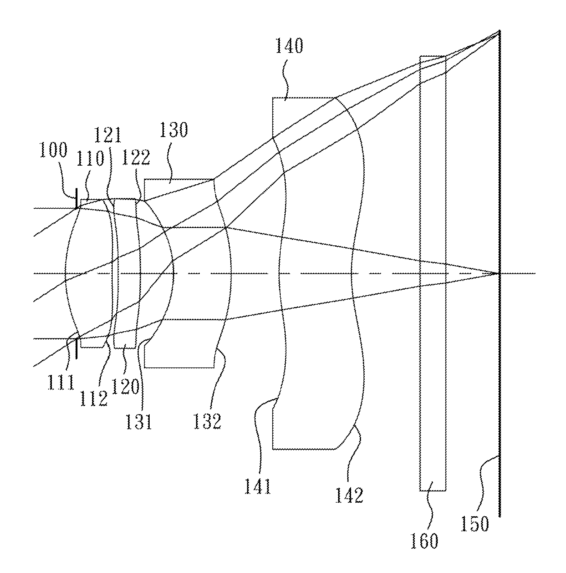
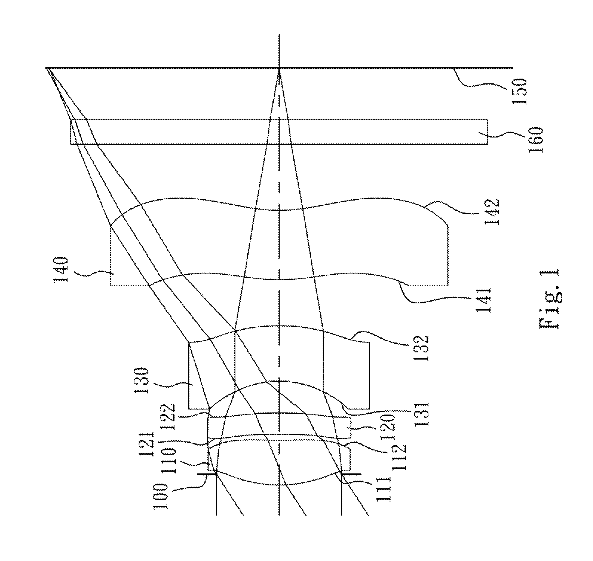
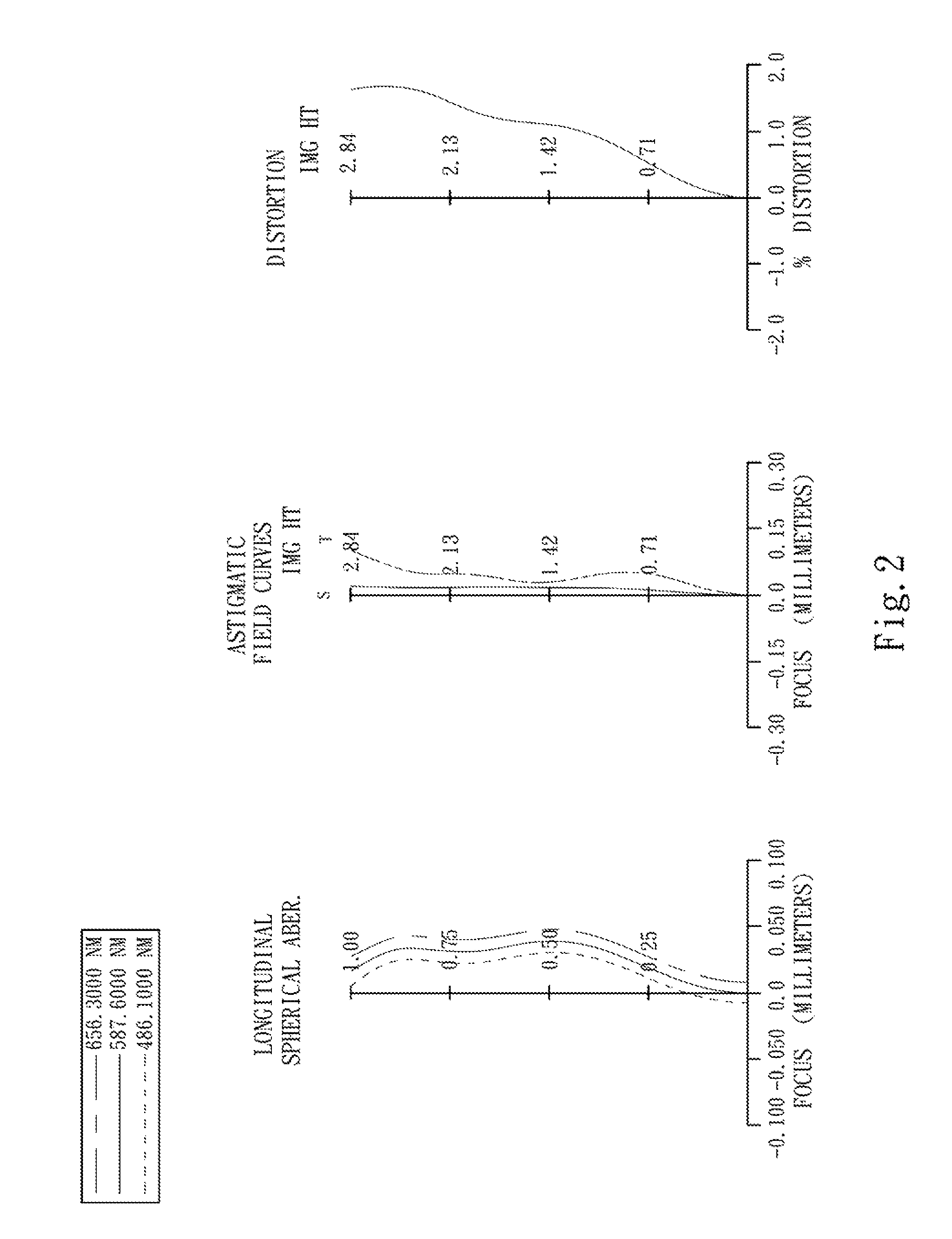
first embodiment
[0065]The equation of the aspheric surface profiles of the aforementioned lens elements of the first embodiment is expressed as follows:
[0066]X(Y)=(Y2 / R) / (1+sqrt(1-(1+k)×(Y / R)2))+Σi(Ai)×(Yi)
[0067]where:
[0068]X is the height of a point on the aspheric surface spaced at a distance Y from the optical axis relative to the tangential plane at the aspheric surface vertex;
[0069]Y is the distance from the point on the curve of the aspheric surface to the optical axis;
[0070]k is the conic coefficient; and
[0071]Ai is the i-th aspheric coefficient.
[0072]In the optical image system according to the first embodiment, when f is a focal length of the optical image system, Fno is an f-number of the optical image system, and HFOV is half of the maximal field of view, these parameters have the following values:
f=4.27 mm;
Fno=2.80; and
HFOV=33.1 degrees.
[0073]In the optical image system according to the first embodiment, when the Abbe number of the first lens element 110 is V1 and the Abbe numb...
second embodiment
[0094]The detailed optical data of the second embodiment are shown in Table 3 and the aspheric surface data are shown in Table 4 below.
[0095]
TABLE 32nd Embodimentf = 4.04 mm, Fno = 2.80, HFOV = 35.0 deg.FocalSurface #Curvature RadiusThicknessMaterialIndexAbbe #length0ObjectPlanoInfinity1Ape. StopPlano−0.1002Lens 11.839730(ASP)0.729Plastic1.54455.93.60325.927100(ASP)0.0724Lens 2−11.990300(ASP)0.300Plastic1.54455.99.635−3.677400(ASP)0.4806Lens 3−0.886370(ASP)0.481Plastic1.63223.4−3.927−1.669840(ASP)0.2388Lens 42.110910(ASP)1.287Plastic1.54455.99.6392.775530(ASP)0.70010IR-filterPlano0.300Glass1.51664.1—11Plano0.52212ImagePlano—Note:Reference wavelength (d-line) is 587.6 nm
[0096]
TABLE 4Aspheric CoefficientsSurface #2345k =−1.40603E+00−1.00000E+00−1.00000E+009.78068E+00A4 =−2.21683E−02−4.60563E−01−5.10091E−01−1.00923E−01A6 =−3.33997E−02−5.48635E−021.33065E−011.12764E−01A8 =1.29747E−015.26833E−016.24645E−011.45161E−01A10 =−4.33012E−01−3.28534E−01−2.98719E−01−3.78370E−01A12 =1.95142E−01−1....
third embodiment
[0106]The detailed optical data of the third embodiment are shown in Table 5 and the aspheric surface data are shown in Table 6 below.
[0107]
TABLE 53rd Embodimentf = 3.88 mm, Fno = 2.95, HFOV = 35.8 deg.FocalSurface #Curvature RadiusThicknessMaterialIndexAbbe #length0ObjectPlanoInfinity1Lens 11.799930(ASP)0.404Plastic1.54455.92.922−12.350900(ASP)−0.0443Ape. StopPlano0.0744Lens 2−39.261900(ASP)0.311Plastic1.54455.912.615−5.858500(ASP)0.3586Lens 3−1.121410(ASP)0.676Plastic1.63423.8−4.997−2.144560(ASP)0.5918Lens 41.913110(ASP)0.861Plastic1.53055.8−316.1691.596640(ASP)1.00010IR-filterPlano0.300Glass1.51664.1—11Plano0.17912ImagePlano—Note:Reference wavelength (d-line) is 587.6 nm
[0108]
TABLE 6Aspheric CoefficientsSurface #1245k =−1.91005E+001.00000E+00−1.00000E+00−1.00000E+00A4 =−3.43741E−02−3.11504E−01−2.68188E−01−1.81235E−01A6 =−1.30667E−01−2.33894E−022.13812E−015.02720E−03A8 =−6.89615E−025.21859E−014.88961E−012.78699E−01A10 =−6.40978E−01−5.42902E−013.58591E−02−7.04995E−01A12 =2.02121E−0...
PUM
 Abstract
Description
Claims
Application Information