Liquid cooler and method of its manufacture

a liquid cooler and manufacturing method technology, applied in the field of heat sinks, can solve the problems of low heat conductivity, labour and manufacturing costs, and inability to obtain the low inner thermal resistance required, and achieve the effect of improving heat removal capacity and enhancing heat transfer

Inactive Publication Date: 2013-05-14
PROFILES SHANGHAI
View PDF17 Cites 2 Cited by
  • Summary
  • Abstract
  • Description
  • Claims
  • Application Information

AI Technical Summary

Benefits of technology

[0012]Accordingly, an object according to the present invention is to provide a liquid cooler with enhanced heat transfer having flow passages with improved heat removal capacity.
[0017]The use of channel systems separated by internal walls formed by said fins of the hollow body on the upper and / or lower side of the insert also improves the capacity to withstand high pressures. With a single channel structure comprising a corresponding volume of liquid the walls of the channels will not be able to withstand the pressure created.

Problems solved by technology

Forming and inserting the cooling fin adds labour and manufacturing cost.
However, this construction gives a low heat conductivity, since the heat transfer has to take place via the brazing material, which has low heat conductivity and therefore it is impossible to obtain the low inner thermal resistance required.
There is however a limit to the height and the pitch of the fins which can be processed; therefore, it is difficult to maintain the cooling capacity of a liquid cooler comprising an extruded heat sink.

Method used


Image

  • Liquid cooler and method of its manufacture
  • Liquid cooler and method of its manufacture
  • Liquid cooler and method of its manufacture

Examples


Embodiment Construction

[0019]Hereinafter, embodiments according to the present invention will be fully explained, by referring to the attached drawings.

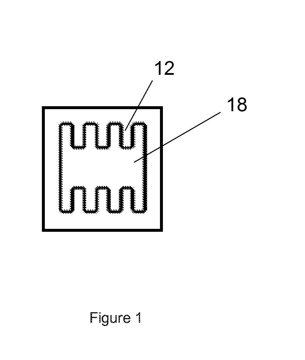
[0020]FIG. 1 is a cross sectional view of the extruded heat sink hollow body.

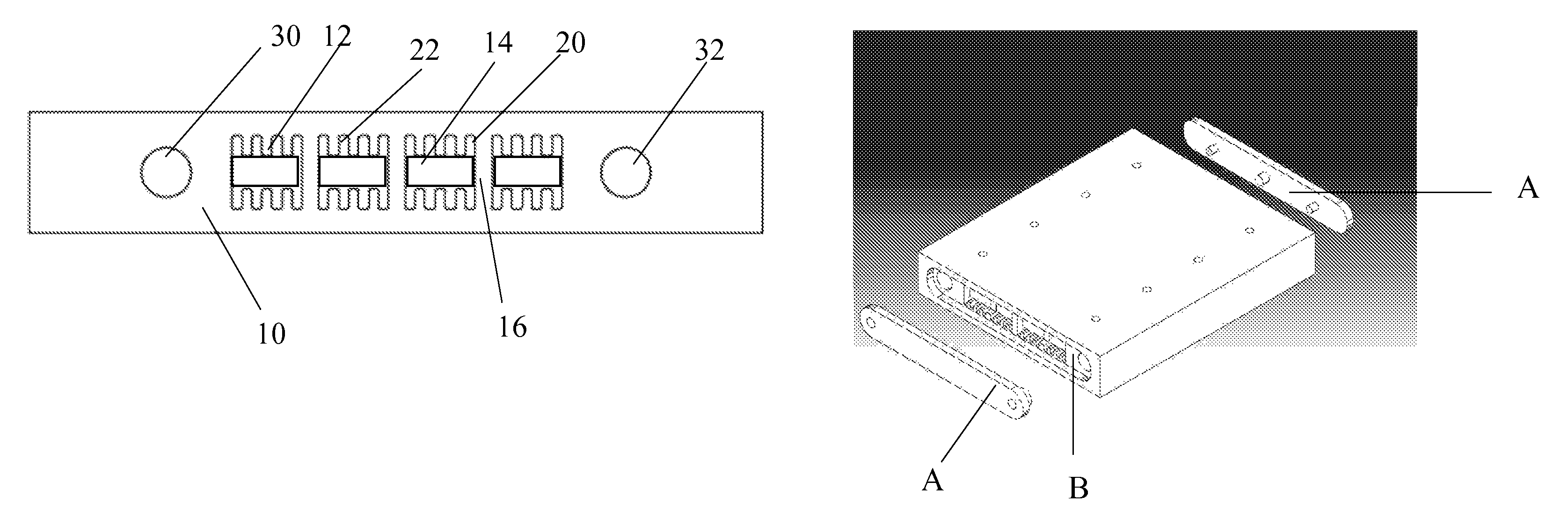
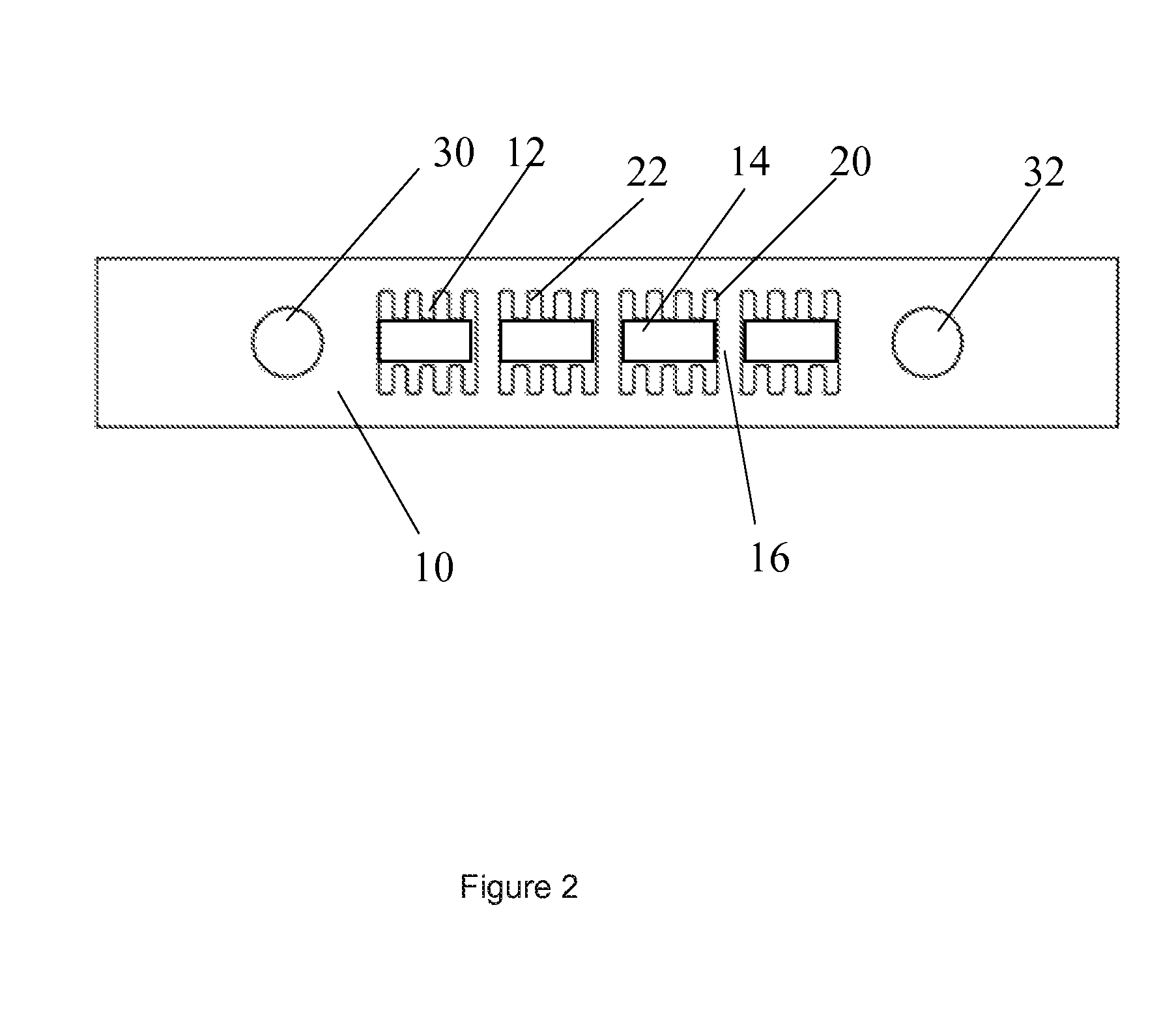
[0021]FIG. 2 is a cross section of a preferred embodiment of the heat sink according to the present invention.

[0022]FIG. 3 is a three dimensional view of an embodiment of the liquid cooler.

[0023]According to a first embodiment, a heat sink is formed by extruding an aluminum billet through a die, to form a hollow body (10) comprising at least one cavity passing through the hollow body, comprising a plurality of supply passages, and having a lid attached to each end of the heat sink. The number of conduits is not limited and may be any suitable number. An even number of conduit leads to the exit of the liquid beeing on the same end of the heat sink as the inlet for the liquid.

[0024]According to a preferred embodiment of the invention the heat sink comprises an inlet conduit (30) and...


PUM

PropertyMeasurementUnit
sizesaaaaaaaaaa
power densityaaaaaaaaaa
heat transferaaaaaaaaaa

Abstract

A liquid cooler including a heat sink. A hollow body is produced by extrusion having at least one flat outer surface between a first and a second end. At least one elongated cavity passes through the body from the first to the second end. The hollow body includes a plurality of parallel fins directed into and along the at least one cavity. An insert housed in the at least one cavity connects the tops of the fins in a fluid-tight manner thereby forming liquid channels for a coolant liquid between the insert and the hollow body. A lid is attached at both ends of the hollow body for forming a liquid cooling system.

Description

CROSS-REFERENCE TO RELATED APPLICATIONS[0001]This application claims priority to Chinese patent application 200810129214.3 filed 20 Jun. 2008 and is the national phase of PCT / SE2009 / 050748 filed 16 Jun. 2009.BACKGROUND OF THE INVENTION[0002]1. Technical Field[0003]The present invention relates to a heat sink to be used in a liquid cooler, and a method of manufacturing the heat sink, a liquid cooler comprising the heat sink and the use of such a cooler.[0004]2. Background Art[0005]Electronic components are continuously improved. The sizes are reduced and the capacity increased. The ever increasing power density entails that also the cooling of such components needs to be improved.[0006]In EP1175135, there is shown a heat sink in which four corrugated fins are respectively inserted into the four through holes and both ends of a casing are closed with covers by brazing. Forming and inserting the cooling fin adds labour and manufacturing cost.[0007]Also in JP2002-170915 a liquid cooling...

Claims


Application Information

Patent Timeline
Patent Type & Authority Patents(United States)
IPC IPC(8): H05K7/20B21D53/02F28F3/14F28F7/00
CPCF28F3/048F28F3/12H01L23/473H05K7/20254Y10T29/4935H01L2924/0002F28F2255/16H01L2924/00
Inventor HOU, JINNYSTROM, HENRIKTUOVINEN, SEPPOLITTLER, DAVIDWANG, YAMIN
Owner PROFILES SHANGHAI
Why Eureka
Try Eureka