Steam heat exchanger

a heat exchanger and steam technology, applied in indirect heat exchangers, refrigeration machines, light and heating equipment, etc., can solve the problems of poor cost reduction effect and difficult drain discharge, and achieve good efficiency

Inactive Publication Date: 2013-05-21
HANAMURA MASAAKI
View PDF13 Cites 1 Cited by
  • Summary
  • Abstract
  • Description
  • Claims
  • Application Information

AI Technical Summary

Benefits of technology

[0011]An object of the present invention is to provide a steam heat exchanger that can perform heat exchange with good efficiency by additionally using sensible heat that is conventionally unused.
[0019]Since a sensible heat transfer part is provided in addition to the condensation heat transfer part in the steam heat exchanger of the present invention, sensible heat can be used, the amount of heat transferred by the heat exchanger can be increased by a commensurate amount, and the amount of steam that is used can be reduced. In this case, the amount of heat that is exchanged is normally significantly reduced because the drain in the condensation heat transfer part may back up and the heat transfer surface may become submerged when the drain discharge amount is merely adjusted, but such an adverse effect does not occur in the present invention.
[0021]Therefore, in accordance with the steam heat exchanger of the present invention, the following effects are obtained.
[0022](a) Heat can be effectively utilized because even the sensible heat of steam can be used without the accompanying danger of water hammering. As a result, an effect can be obtained in which the amount of primary-side steam flow is reduced and the load on a steam generation source such as a boiler can be alleviated.
[0023](b) By taking into account the surface area of the sensible heat transfer part, steam can be used at a high pressure without diminishing thermal efficiency. The resulting effect is that a drain recovery apparatus such as a vacuum pump is unnecessary on the drain recovery side and that the diameter of a steam control valve or steam pipe can be made smaller.
[0024](c) By taking into account the surface of the sensible heat transfer part, re-evaporation inside a drain conduit can be prevented. For this reason, an effect can be obtained in which the diameter of a condensate pipeline can be made smaller and the radiation loss from the condensate pipeline can be greatly decreased because the drain temperature is also low.

Problems solved by technology

In these cases, only flash steam can be used to prevent water hammering, and it is often the case that the cost-reducing effect is poor because there are limitations to the pressure of a drain recovery pipe.
As a result, smooth drain discharge becomes difficult and there are many cases in which positional proportional control has no significance.

Method used


Image

  • Steam heat exchanger
  • Steam heat exchanger
  • Steam heat exchanger

Examples


embodiment 1

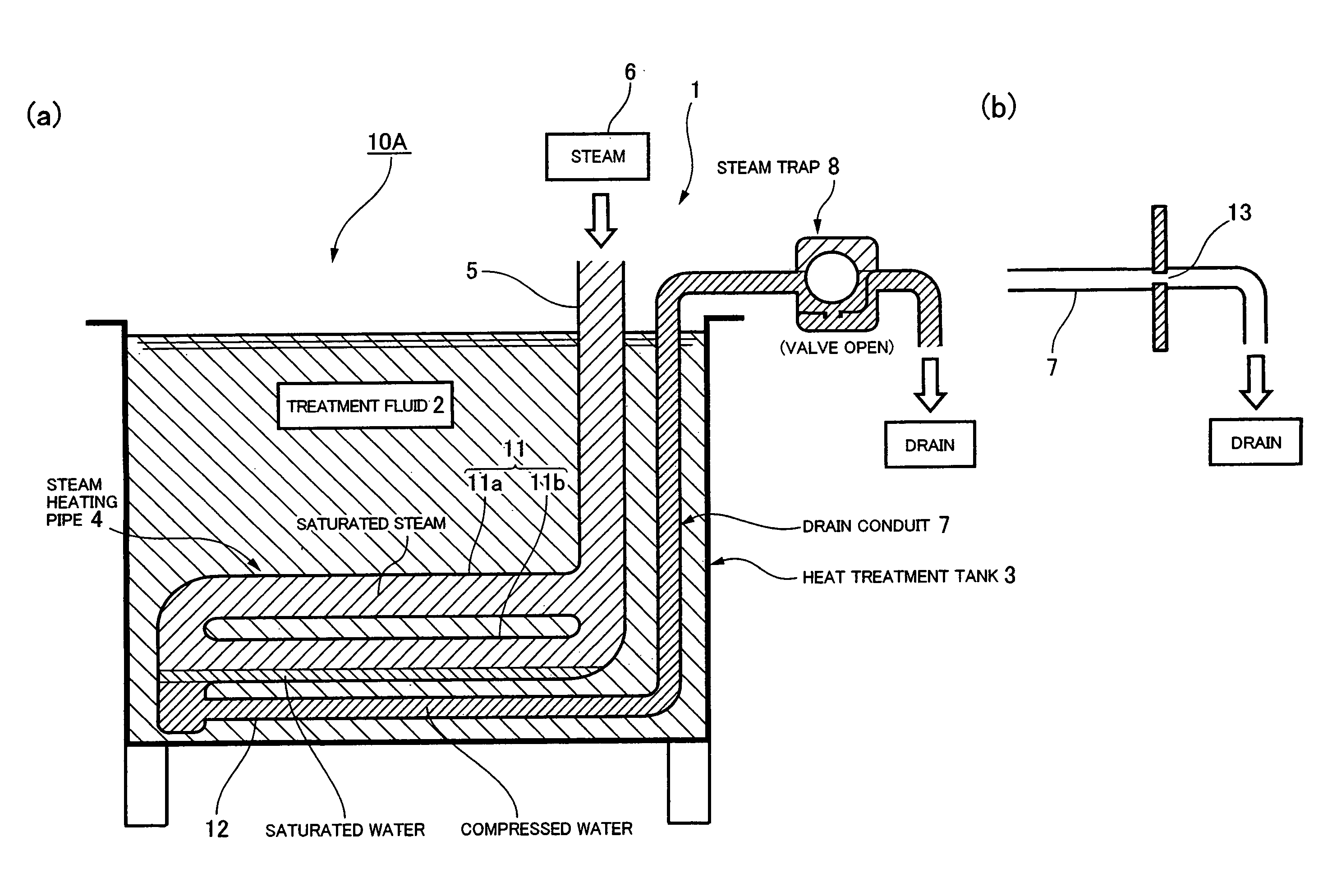
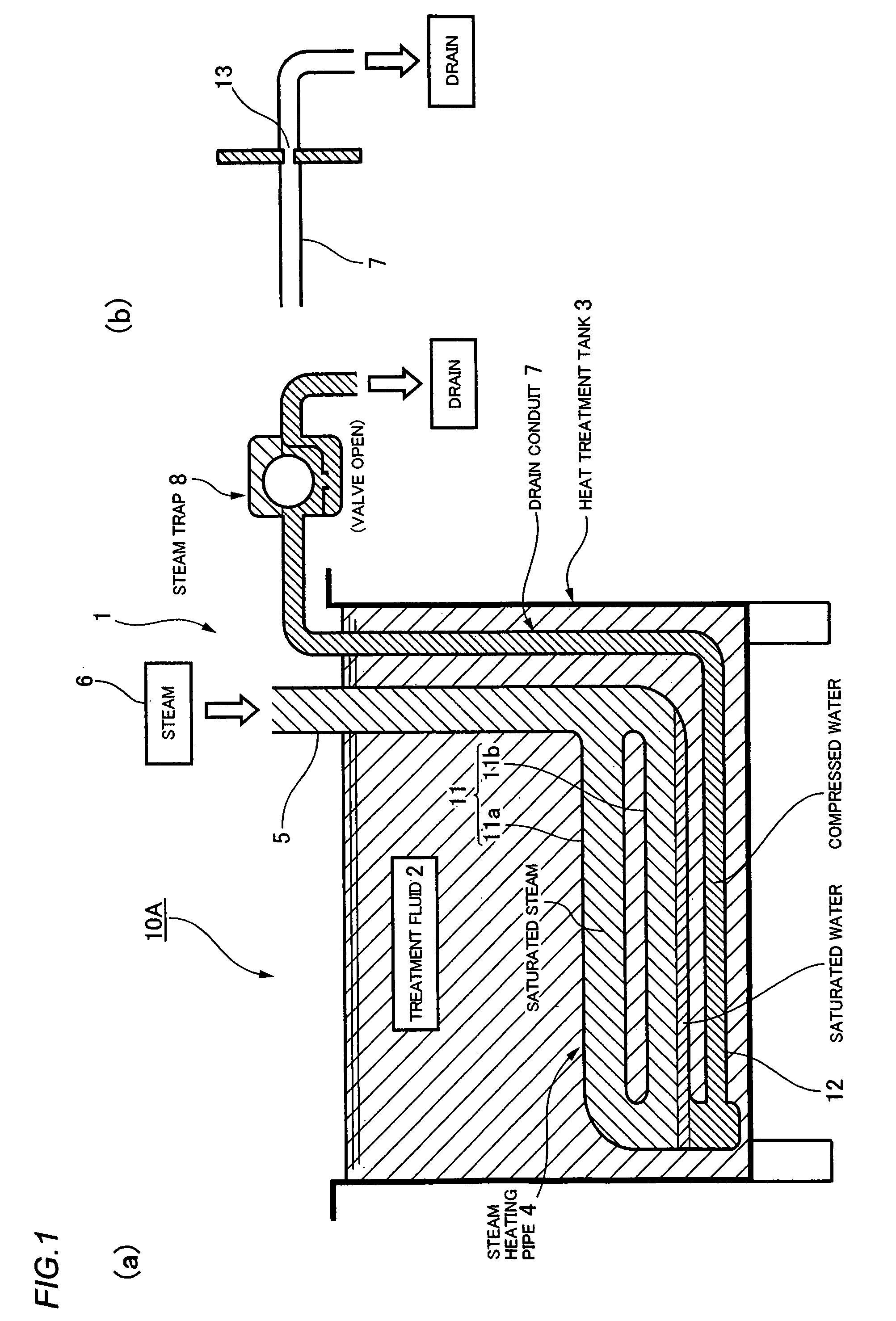
[0035]FIG. 1(a) is a schematic structural diagram showing a heating system provided with the steam heat exchanger to which the present invention has been applied. A steam heat exchange system 10A has a steam heat exchanger 1 and an open heat treatment tank 3 which holds the treatment fluid 2 of the heating object. The steam heat exchanger 1 has a steam heating pipe 4 in the form of an accordion which is horizontally disposed in the vicinity of the bottom surface of the heat treatment tank 3. A steam supply pipe 5 stands vertically erect from the end part of the upstream side of the steam heating pipe 4, and steam having a prescribed temperature is supplied through this steam supply pipe 5 from a boiler or another steam generation source 6. A drain conduit 7 stands vertically erect from the end part of the downstream side of the steam heating pipe 4, and the drain is evacuated through the drain conduit 7 and a steam trap 8.

[0036]The steam heating pipe 4 is provided with a plurality o...

embodiment 2

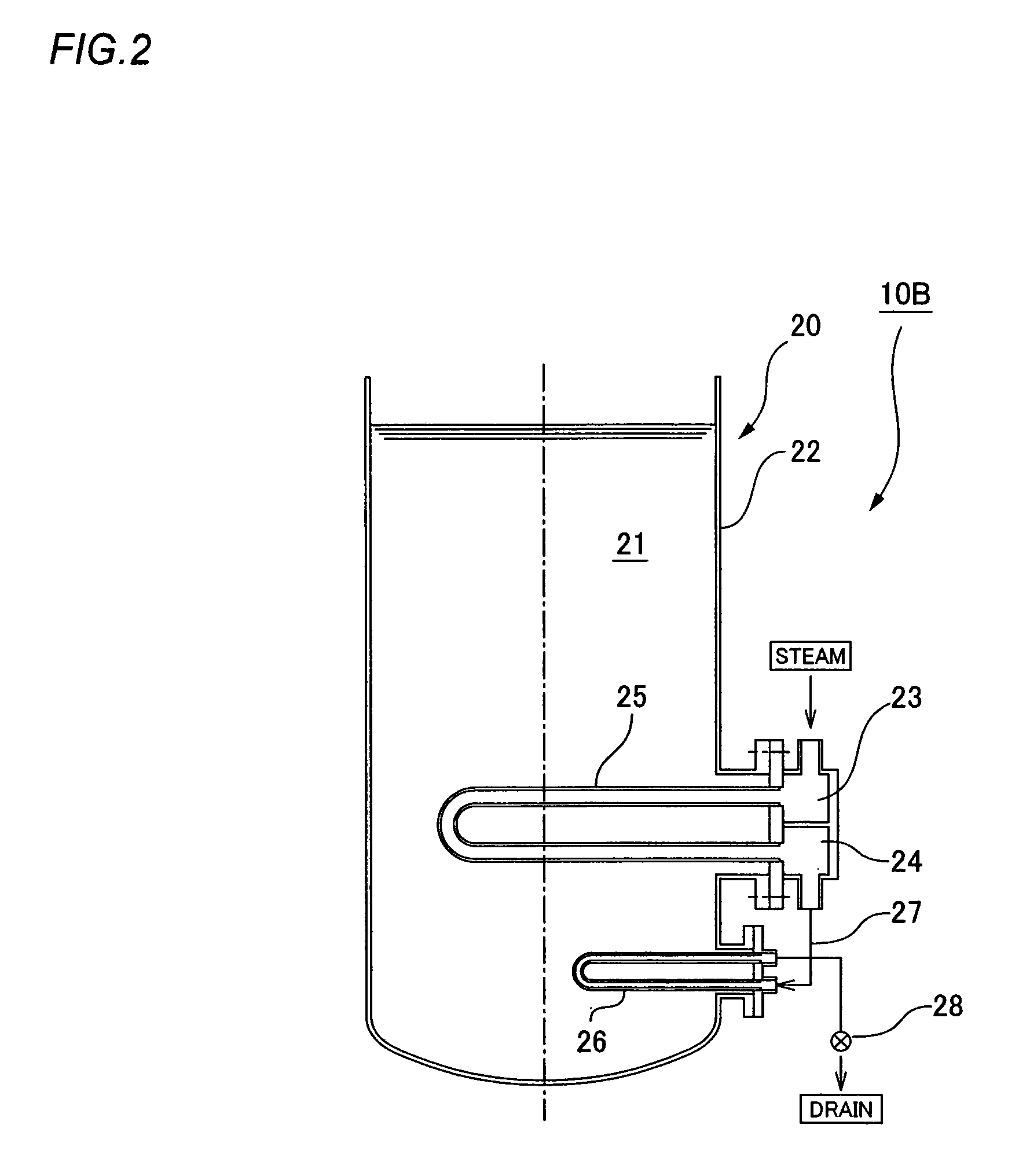
[0043]FIG. 2 is a schematic structural diagram showing a separate example of a steam heat exchange system provided with a steam heat exchanger in which the present invention has been applied. A steam heat exchange system 10B has a steam heat exchanger 20 and a vertically arranged open tank 22 that holds a treatment fluid 21. The steam heat exchanger 20 is provided with a steam supply port 23 and discharge port 24 mounted on the side part of the open tank 22, a U-shaped condensation heat transfer pipe 25 that extends horizontally toward the interior from the steam supply port and discharge port, and a U-shaped sensible heat transfer pipe 26 that extends horizontally toward the interior of the open tank in the same manner on the lower side of the heat transfer pipe 11. The upstream end of the sensible heat transfer pipe 26 is in communication with the discharge port 23 via the pipe 27 outside of the open tank 22, and the downstream end of the sensible heat transfer pipe 26 is in commu...


PUM


Abstract

A steam heat exchanger includes a steam heating pipe with a condensation pipe part and a sensible heat pipe part provided on the lower side of the condensation pipe part. In the condensation pipe part, a liquid is heated by latent heat. The drain discharge capacity in a steam trap or an orifice disposed on the drain discharge side equals the amount of condensation at the service temperature of the steam heat exchanger. Condensed water produced after the heat exchange in the condensation pipe part enters the sensible heat pipe part on the downstream side to hold the sensible heat pipe part in a water sealed state. In this sensible heat pipe part, the liquid is heated by sensible heat. Heat exchange efficiency is improved by using latent and sensible heat, the amount of steam used can be reduced, and the load of a steam generation source can be reduced.

Description

TECHNICAL FIELD[0001]The present invention relates to a steam heat exchanger suitable for use in heating a heat treatment tank used in metal plating treatment and the like, and more specifically relates to a steam heat exchanger that can heat a heating object with good efficiency using a low amount of steam by making use of sensible heat.BACKGROUND ART[0002]The heat treatment tank of a workpiece used in metal plating treatment and the like uses a steam heat exchanger having a configuration in which a steam heating pipe is disposed on the bottom side of the tank interior, and the workpiece inside the heat treatment tank filled with a treatment liquid is heated. An example of a conventional steam heat exchanger disposed in an open treatment tank is shown in FIGS. 3 and 4.[0003]The steam heat exchanger 100 shown in FIG. 3 is a lift-fitting steam heat exchanger and has a steam heating pipe 103 drawn about in the form of an accordion so as to be two-tiered in the vertical direction in a ...

Claims


Application Information

Patent Timeline
Patent Type & Authority Patents(United States)
IPC IPC(8): F25B1/02
CPCF28B1/02F28D1/0213F28B9/08F28D1/06
Inventor HANAMURA, MASAAKI
Owner HANAMURA MASAAKI
Why Eureka
Try Eureka