Linear type vibration motor having magnet casing

a magnet casing and vibration motor technology, applied in the direction of dynamo-electric machines, dynamo-electric components, magnetic circuit shapes/forms/construction, etc., can solve the problems of short operating life of motors using brushes and commutators, wear and black powder, and slow response to touch on touch screen, so as to achieve less vulnerable to vibration and shock, and long operating life

Inactive Publication Date: 2013-05-21
SAMSUNG ELECTRO MECHANICS CO LTD
View PDF11 Cites 11 Cited by
  • Summary
  • Abstract
  • Description
  • Claims
  • Application Information

AI Technical Summary

Benefits of technology

[0017]The present invention provides a linear type vibration motor having a magnet casing that is less vulnerable to vibrations and shocks and has a long operating lifetime.
[0020]At least one fixing protrusion can be formed on both ends of the magnet casing, and the fixing protrusion can fix the magnet assembly by being bent toward a central axis of the magnet casing such that the magnet assembly is prevented from being detached.

Problems solved by technology

The vibration motor using such brush and commutator has a shorter operating lifetime due to mechanical friction and electrical sparks, which cause wear and black powder, while the brush moves between the segments of the commutator when the motor rotates.
Moreover, when voltage is supplied to the vibration motor, it takes time to reach the target amount of vibration, i.e., the magnitude by which it is sufficient for the user to sense the vibration, by the rotational inertia of the vibration motor, causing a slower response to the touch made on the touch screen.
This may cause malfunction of the linear type vibration motor.

Method used


Image

  • Linear type vibration motor having magnet casing
  • Linear type vibration motor having magnet casing
  • Linear type vibration motor having magnet casing

Examples


Embodiment Construction

[0028]As the invention allows for various changes and numerous embodiments, particular embodiments will be illustrated in the drawings and described in detail in the written description. However, this is not intended to limit the present invention to particular modes of practice, and it is to be appreciated that all changes, equivalents, and substitutes that do not depart from the spirit and technical scope of the present invention are encompassed in the present invention. In the description of the present invention, certain detailed descriptions of related art are omitted when it is deemed that they may unnecessarily obscure the essence of the invention.

[0029]The features and advantages of this invention will become apparent through the below drawings and description.

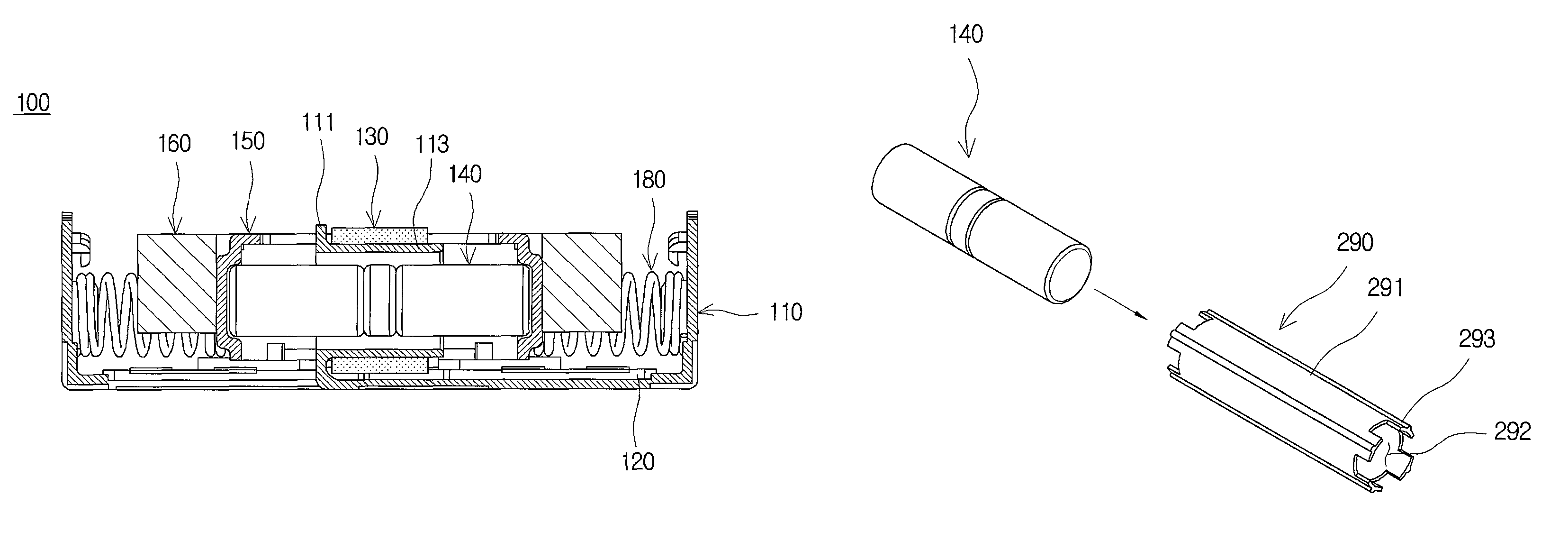
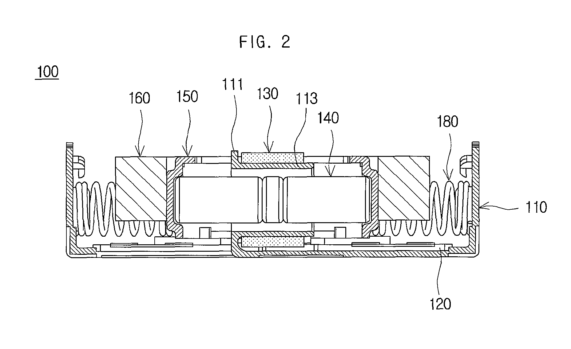
[0030]FIG. 2 is a cross-sectional view of a linear type vibration motor.

[0031]Referring to FIG. 2, a linear type vibration motor 100 includes a base 110, a substrate 120, a coil 130, a magnet assembly 140, a yoke 150, ...


PUM


Abstract

A linear type vibration motor having a magnet casing is disclosed. The linear type vibration motor in accordance with an embodiment of the present invention includes a magnet assembly having a pair of magnets, in which same magnetic poles thereof face each other, a magnet casing, which has a hollow part formed therein and houses the magnet assembly in the hollow part, a base, which has a bobbin formed thereon and in which the magnet casing is inserted into the bobbin, a coil, which is coupled to the bobbin, a weight, which is coupled to both ends of the magnet casing, and a pair of elastic bodies, which are interposed between either end of the base and either end of the weight, respectively. Thus, the operating lifetime of the linear type vibration motor can be extended, and this arrangement can prevent the linear type vibration motor from being damaged by an external shock.

Description

CROSS-REFERENCE TO RELATED APPLICATIONS[0001]This application claims the benefit of Korean Patent Application No. 10-2009-0065921, filed with the Korean Intellectual Property Office on Jul. 20, 2009, the disclosure of which is incorporated herein by reference in its entirety.BACKGROUND[0002]1. Technical Field[0003]The present invention is related to a linear type vibration motor having a magnet casing.[0004]2. Description of the Related Art[0005]A vibration motor is a part that converts electrical energy into mechanical vibrations by using the principle of generating electromagnetic forces, and is commonly installed in a mobile phone to generate a soundless vibrating alert. With the rapid expansion of mobile phone markets and increased functionalities added to the mobile phone, mobile phone parts are increasingly required to be smaller and better. As a result, there has been an increased demand for the development of a new structure of vibration motor that can overcome the shortcomi...

Claims


Application Information

Patent Timeline
Patent Type & Authority Patents(United States)
IPC IPC(8): H02K33/16H02K33/00
CPCH02K1/34H02K33/16H02K33/02H02K35/02
Inventor JUN, JAE-WOOCHOI, JUN-KUNOH, HWA-YOUNGLEE, JEE-SUNGKIM, YONG-JINLEE, KYUNG-HOPARK, SEOK-JUNLEE, KWANG-HYUNGBANG, JE-HYUN
Owner SAMSUNG ELECTRO MECHANICS CO LTD
Why Eureka
Try Eureka