Spring sleeve for fuel injector

a fuel injector and spring sleeve technology, which is applied in the direction of ring springs, combustion types, lighting and heating apparatus, etc., can solve the problems of undesirable leakage at the thread, complex production of threads on the inside of the nozzle clamping nut and on the outer circumference surface of the holding body, etc., to increase the ruggedness of the spring sleeve, the effect of increasing the local stress

Inactive Publication Date: 2013-05-21
ROBERT BOSCH GMBH
View PDF14 Cites 0 Cited by
  • Summary
  • Abstract
  • Description
  • Claims
  • Application Information

AI Technical Summary

Benefits of technology

[0009]During injector operation, individual differential distances d1 through d7 are produced, which differ from one another when subjected to dynamic stress as opposed to static stress. They vary in a chronological sequence. Under a static load, the differential distances d1 through d7 are the same size as one another and each correspond to a fraction of the total length of the spring sleeve.
[0013]The differential distances and therefore the local dynamic stress of the open spring sleeve proposed according to the invention is higher in the edge region and decreases toward its middle. The optimized embodiment of the open spring sleeve proposed according to the invention therefore makes it possible to increase the ruggedness of the spring sleeve so that it is able to withstand a higher local stress particularly in the edge region. As a result, stress cycle numbers of >1.2×10⁹ load changes can occur without damage to the component during operation of the fuel injector.
[0017]In a second advantageous embodiment of the design proposed according to the invention, in lieu of a variation of the wall thickness of the open spring sleeve as a function of the longitudinal direction, a modification of the embodiment of holes in the circumferential surface of the open spring sleeve is provided. In the open spring sleeve proposed according to the invention, whose abutting ends form a dividing seam, a first hole geometry and a second hole geometry are provided in alternating sequence. As a function of the longitudinal direction of the open spring sleeve, both the first and second hole geometries can be embodied in terms of their width between a first width S1,min and S1,max with regard to a first hole geometry and can be embodied with regard to a minimum width S2,min and a maximum width S2,max with regard to a second hole geometry.
[0015]According to a first advantageous embodiment of the design proposed according to the invention, it is possible to vary the wall thickness of the material of the open spring sleeve. Preferably, the wall thickness of the open spring sleeve proposed according to the invention is varied in the longitudinal direction; it is possible for either the inner diameter of the open spring sleeve or the outer diameter of the open spring sleeve to vary. It is also possible for both the inner and outer diameter of the spring sleeve to vary. Preferably, the variation of the wall thickness is embodied so that there is a difference of approx. 20% between the minimum and maximum wall thickness of the material of the open spring sleeve.
[0006]In fuel injectors that have been used up to this point, a screw connection is produced by means of a clamping nut, which connects a nozzle body, a throttle plate resting against it, and a valve plate of the fuel injector to the holding body of the fuel injector. Firstly, it is of secondary importance whether the fuel injector is actuated by means of a piezoelectric actuator or by means of a solenoid valve. In general, a sealing ring preferably made of PTFE is used to seal the low-pressure region of the fuel injector in relation to the outside. In order to attach the nozzle clamping nut—which as a rule encompasses a nozzle body, a nozzle plate, and a valve plate—to the holding body, a thread is embodied on the inside of the nozzle clamping nut. By means of this thread, the prestressing force produces a screw-connected assembly composed of the holding body and nozzle body as well as the components inserted between them. The production of the thread on the inside of the nozzle clamping nut on the one hand and on the outer circumference surface of the holding body on the other hand is complex and expensive; in addition, an undesirable leakage can occur at the thread and an unevenly distributed action of the prestressing force introduced into the screw-connected assembly by the clamping torque of the thread.
[0017]In a second advantageous embodiment of the design proposed according to the invention, in lieu of a variation of the wall thickness of the open spring sleeve as a function of the longitudinal direction, a modification of the embodiment of holes in the circumferential surface of the open spring sleeve is provided. In the open spring sleeve proposed according to the invention, whose abutting ends form a dividing seam, a first hole geometry and a second hole geometry are provided in alternating sequence. As a function of the longitudinal direction of the open spring sleeve, both the first and second hole geometries can be embodied in terms of their width between a first width S1,min and S1,max with regard to a first hole geometry and can be embodied with regard to a minimum width S2,min and a maximum width S2,max with regard to a second hole geometry.
[0018]According to the variation of the hole geometry as a function of the longitudinal direction proposed according to the invention, the width of both the first hole geometry and the second hole geometry in the edge region of the open spring sleeve proposed according to the invention amounts to only approx. 80% of the hole width in the middle.
[0019]Through the variation of the hole width as a function of the longitudinal direction carried out in the second embodiment of the present invention, the open spring sleeve proposed according to the invention is stiffened in the edge region, correspondingly reducing the local deformations in this region.
[0020]The result is a more homogeneous stressing of the open spring sleeve when it is subjected to a dynamic load during operation of the fuel injector. In order not to change the overall rigidity, i.e. the spring rate, of the open spring sleeve, it is necessary to assure that the middle hole width or the middle wall thickness according to the first embodiment corresponds approximately to the value of the width of the holes with a constant hole width of both the first hole geometry and the second hole geometry.

Problems solved by technology

The production of the thread on the inside of the nozzle clamping nut on the one hand and on the outer circumference surface of the holding body on the other hand is complex and expensive; in addition, an undesirable leakage can occur at the thread and an unevenly distributed action of the prestressing force introduced into the screw-connected assembly by the clamping torque of the thread.

Method used


Image

  • Spring sleeve for fuel injector
  • Spring sleeve for fuel injector
  • Spring sleeve for fuel injector

Examples


Embodiment Construction

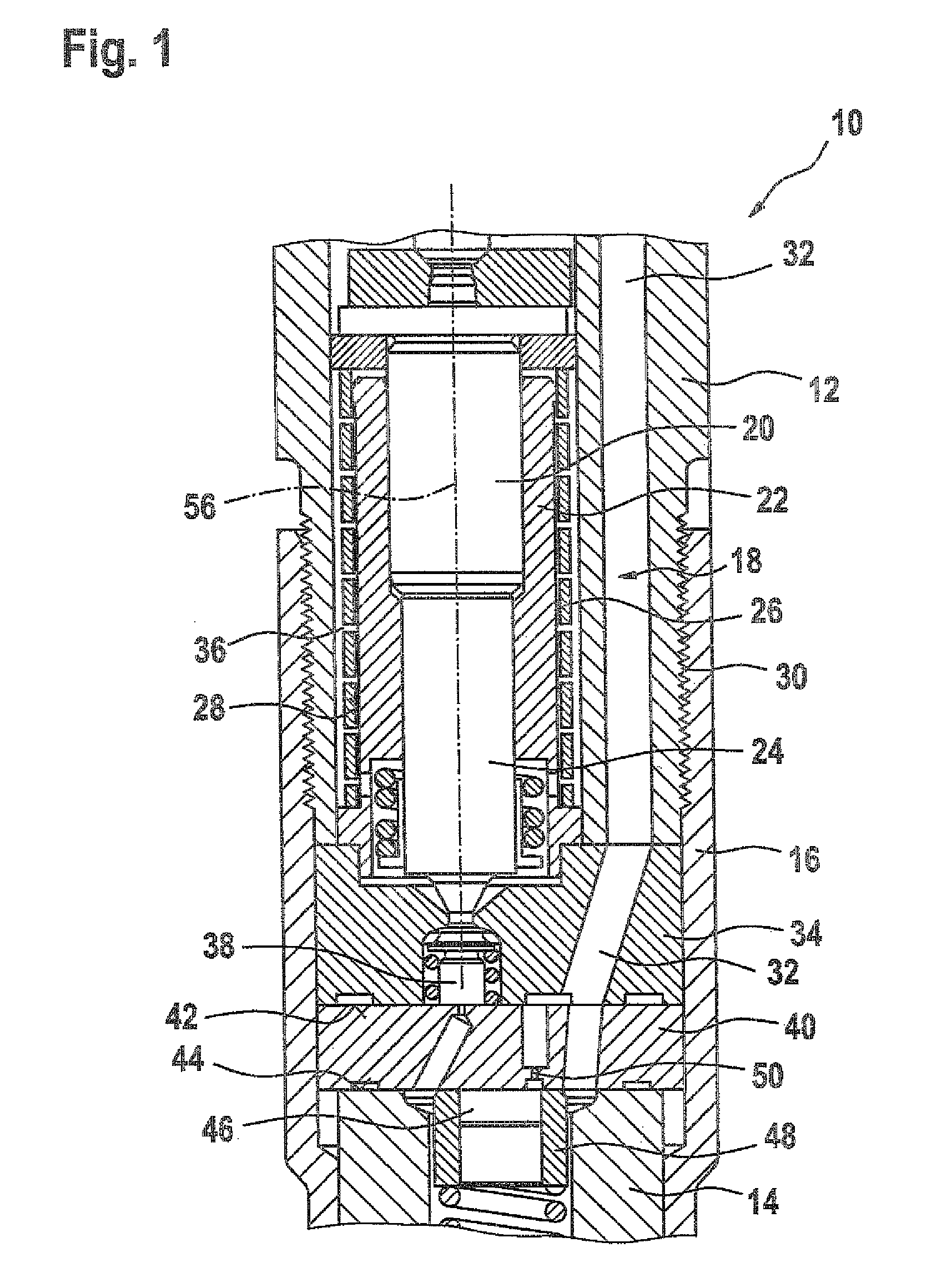
[0027]FIG. 1 shows a section through a fuel injector according to the prior art, which includes a coupler module.

[0028]FIG. 1 shows a fuel injector 10 that includes a holding body 12 and a nozzle body 14. The holding body 12 and the nozzle body14 are connected to each other via a nozzle clamping nut 16. The holding body 12 has a cavity 36 in which a coupler module 18 is accommodated.

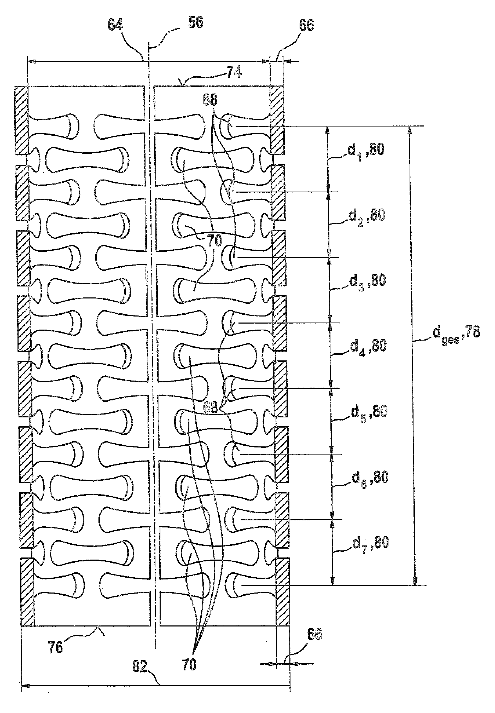
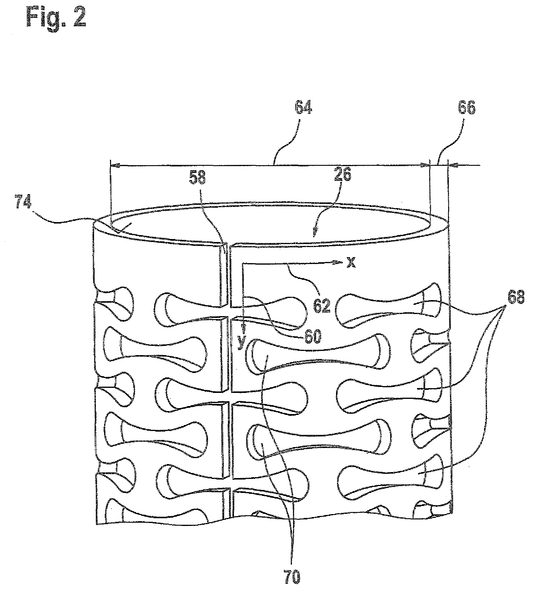
[0029]The coupler module 18 includes a coupler piston 20 and a coupler body 22. The coupler body 22 encompasses both the coupler piston 20 and a piston 24 on which the coupler piston 20 acts. A circumference surface 28 of the coupler body 22 is encompassed by a spring sleeve 26.

[0030]It is clear from the sectional depiction according to FIG. 1 that the holding body 12 and the nozzle body 14 are connected to each other at a screw connection 30, with the interposition of a valve plate 34 and the throttle plate 40. An inlet 32 extends through the holding body 12, the valve plate 34, and the throttle plate 4...


PUM


Abstract

The invention relates to a fuel injector with a holding body and a nozzle body which are joined together and which accommodate a coupler module which has a coupler body enclosed by a spring sleeve. The spring sleeve is open in a circumferential direction at a seam thereof which extends in the longitudinal direction. Either the wall thickness of the spring sleeve varies in the longitudinal direction, or a width of at least one hole geometry in the sheathing of the spring sleeve varies in the longitudinal direction.

Description

CROSS-REFERENCE TO RELATED APPLICATION[0001]This application is a 35 USC 371 application of PCT / EP2008 / 051124 filed on Jan. 30, 2008.BACKGROUND OF THE INVENTION[0002]1. Field of the Invention[0003]The invention relates to a fuel injector with a holding body and a nozzle body.[0004]2. Description of the Prior Art[0005]DE 196 50 865 A1 has disclosed a solenoid valve for controlling the fuel pressure in a control chamber of an injection valve, for example in a common rail / high-pressure accumulator injection system. The fuel pressure in the control chamber is used to control a stroke motion of a valve piston by means of which an injection opening of the injection valve is opened or closed. The solenoid valve includes an electromagnet, a movable armature, and a valve element that is moved by the armature, is acted on in the closing direction by a valve closing spring, and cooperates with the valve seat of the solenoid valve, thus controlling the flow of fuel out of the control chamber.[0...

Claims


Application Information

Patent Timeline
Patent Type & Authority Patents(United States)
IPC IPC(8): H02N1/00
CPCF02M47/027F02M61/16F02M63/007F16F1/028F02M2200/701F02M2547/001F16F2230/36F02M47/02F02M63/00F16F1/02
Inventor UHLMANN, DIETMARLOUTRAGE, JEAN-LUC
Owner ROBERT BOSCH GMBH
Why Eureka
Try Eureka