Ion eluting unit and device loaded with same

a technology of elution unit and electrode, which is applied in the direction of instruments, water/sewage treatment by electrochemical methods, other washing machines, etc., can solve the problems of uneven depletion of electrodes and inability to elution metal ions, and achieve the effect of elution stably

Active Publication Date: 2013-05-28
SHARP KK
View PDF28 Cites 0 Cited by
  • Summary
  • Abstract
  • Description
  • Claims
  • Application Information

AI Technical Summary

Benefits of technology

[0008]On cathode side, on the other hand, a reaction of H++e−→½H2 takes place regardless of the material of the electrode resulting in the generation of hydrogen gas and the deposition of compound of calcium contained in water as a scale on the surface of the electrode. Chloride or sulfide of the component metal is also precipitated on the electrode surface. Consequently, after the electrodes are used for a long time, a thick accumulation of scale, chloride or sulfide are formed on the surface of the cathode electrode. This accumulation hinders elution of metal ions, leading to unstable elution of metal ions and uneven depletion of electrodes.
[0036]Alternatively, according to the present invention, in an ion elution unit that generates silver ions by applying a voltage between silver electrodes disposed in a water feed passage, polarities of the electrodes are reversed cyclically. With this configuration, silver ions are eluted into the water fed via the water feed passage and attach to the objects for which the water is used, and the objects are sterilized and the mold on them is removed. And precipitation of scale or other substances is prevented by polarity reversal, and thereby silver ions are eluted stably.

Problems solved by technology

This accumulation hinders elution of metal ions, leading to unstable elution of metal ions and uneven depletion of electrodes.

Method used


Image

  • Ion eluting unit and device loaded with same
  • Ion eluting unit and device loaded with same
  • Ion eluting unit and device loaded with same

Examples


Embodiment Construction

[0054]An embodiment of the present invention will be described with reference to Figures.

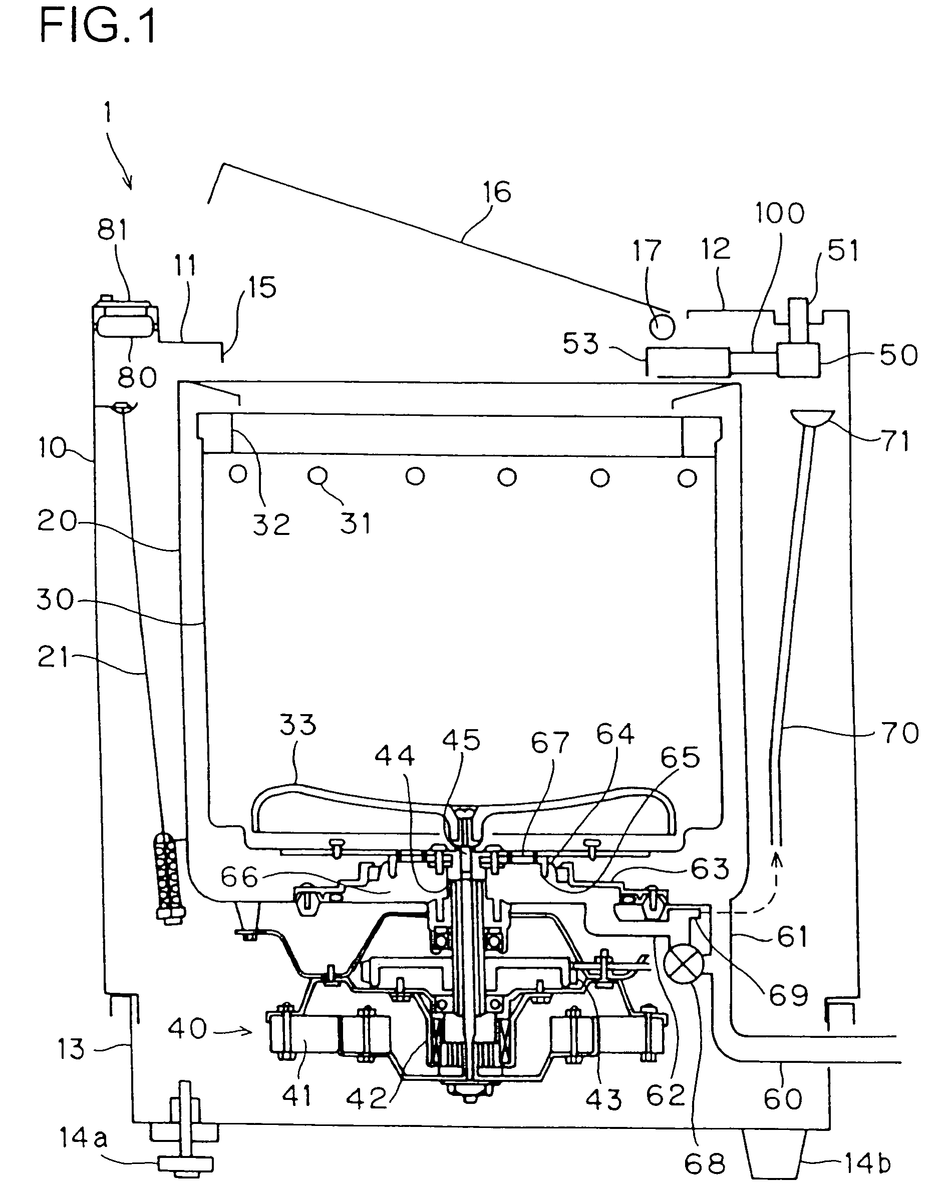
[0055]FIG. 1 is a vertical sectional view showing the overall construction of a washer 1. The washer 1 is of an automatic type, and has a cabinet 10. The box-shaped cabinet 10 is formed of metal or synthetic resin, and has openings at its top and bottom. The top opening of the cabinet 10 is covered with a top plate 11, which is formed of synthetic resin and is fixed to the cabinet 10 with screws. In FIG. 1, front and rear of the washer 1 point leftward and rightward, respectively. A rear portion of a top surface of the top plate 11 is covered with a back panel 12, which is formed of synthetic resin and is fixed to the cabinet 10 or the top plate 11 with screws. The bottom opening of the cabinet 10 is covered with a base 13, which is formed of synthetic resin and is fixed to the cabinet 10 with screws. None of the screws mentioned thus far are shown in the figure.

[0056]Feet 14a and 14b for suppor...


PUM

PropertyMeasurementUnit
thickaaaaaaaaaa
thickaaaaaaaaaa
thickaaaaaaaaaa

Abstract

In an ion elution unit, a drive circuit applies a voltage between electrodes to elute metal ions from the electrodes. Polarities of the electrodes are reversed cyclically with a voltage application halt period placed in-between. A current detection circuit detects the current flowing between the electrodes. A check of operation of the current detection circuit is carried out before the application of a voltage to the electrodes is started. The operation of the current detection circuit is started when a predetermined period of time passes after the application of a voltage to the electrodes is started.

Description

TECHNICAL FIELD[0001]The present invention relates to an ion elution unit for eluting metal ions having an antimicrobial effect into water, and also relates to an appliance, in particular a washer, that uses water mixed with metal ions generated by such ion elution unit.BACKGROUND ART[0002]When laundry is washed in a washer, it is common to add a treatment substance to water, in particular, to rinsing water. Typical examples of such treatment substances include softening and starching agents. In addition to these, in recent years, the demand has been increasing for treatment whereby laundry is subjected to antimicrobial treatment.[0003]From the hygienic point of view, it is desirable to hang laundry in the sun to dry. However, in recent years, with the increase in the number of women who go to work, and with the increase in the number of nuclear families, there have been an increasing number of households where no one is at home in the daytime. In these households, there is no choic...

Claims


Application Information

Patent Timeline
Patent Type & Authority Patents(United States)
IPC IPC(8): D06F35/00G01N27/416C02F1/46D06F33/02D06F39/00D06F39/02D06F39/08
CPCC02F1/4606D06F39/088D06F33/02D06F35/003D06F35/006D06F39/02C02F2201/46125C02F2201/4613C02F2201/46145C02F2201/4615C02F2303/24
Inventor OOE, HIROKAZUTATEYAMA, YUTAKAKAMII, TOSHIHIRO
Owner SHARP KK
Why Eureka
Try Eureka