Ultra-miniature electro-mechanical safety and arming device

a technology of electro-mechanical safety and arming device, which is applied in the direction of ammunition fuzes, weapons, weapon components, etc., can solve the problems of high danger condition, size, reliability, cost, and the optimum possible fuze size, and achieves the effect of less costly, more reliable, and simple structur

Inactive Publication Date: 2013-05-28
UNITED STATES OF AMERICA THE AS REPRESENTED BY THE SEC OF THE ARMY
View PDF12 Cites 6 Cited by
  • Summary
  • Abstract
  • Description
  • Claims
  • Application Information

AI Technical Summary

Benefits of technology

[0011]The present invention is an ultra-miniature electro-mechanical, MEMS, safety and arming (S&A) device for gun-launched munitions, i.e. projectiles, that has a footprint of approximately 7×10 mm, and a lower profile or side elevation than the prior art, the '231 fuze, such that it is over 30% smaller by volume. Further, the present invention, eliminates the complex three dimensional lock rocker assembly of the '231 fuze, replacing its functionality with a simple, two dimensional, stop and release mechanism, described below. These and other changes are provided in the present invention, which maintains the full safety functionality of the prior art, in a physically smaller, simpler, more reliable, and less costly device.
[0016]In an alternative embodiment, detailed below, the functionality of the fourth layer is incorporated in the third layer, such that the third layer contains the S&A mechanism and the output charge. In this embodiment, a transfer charge within the third S&A mechanism layer, the same transfer charge included in the S&A mechanism layer in all of the other embodiments, is aligned adjacent to the output charge and separated therefrom by only thin membranes—such that when the three S&A interlocks are cleared, the firetrain will trigger the transfer charge, and the transfer charge will trigger the adjacent output charge; which will trigger the acceptor charge external to the S&A device. This alternative embodiment, further miniaturizes and simplifies the subject S&A device, leading to further cost savings and reliability.

Problems solved by technology

The premature detonation of munitions, including artillery rounds, bombs, missiles, and / or mortar shells during handling, shipping, or in storage creates a highly dangerous condition.
A prototype '231 fuze has a footprint of approximately 10×10 mm, a relatively large footprint; a rather complex means whereby an independent setback slider initially frees an arming slider; a certainly complex three dimensional lock rocker assembly which finally releases the arming slider to proceed to its armed position, all of which are certainly significant advantages versus conventional (non-MEMS-based) fuzes of the prior art; but there still exist problems in size, reliability, complexity, and cost, regarding the optimum possible fuze, to meet the stated criteria.

Method used


Image

  • Ultra-miniature electro-mechanical safety and arming device
  • Ultra-miniature electro-mechanical safety and arming device
  • Ultra-miniature electro-mechanical safety and arming device

Examples


first embodiment

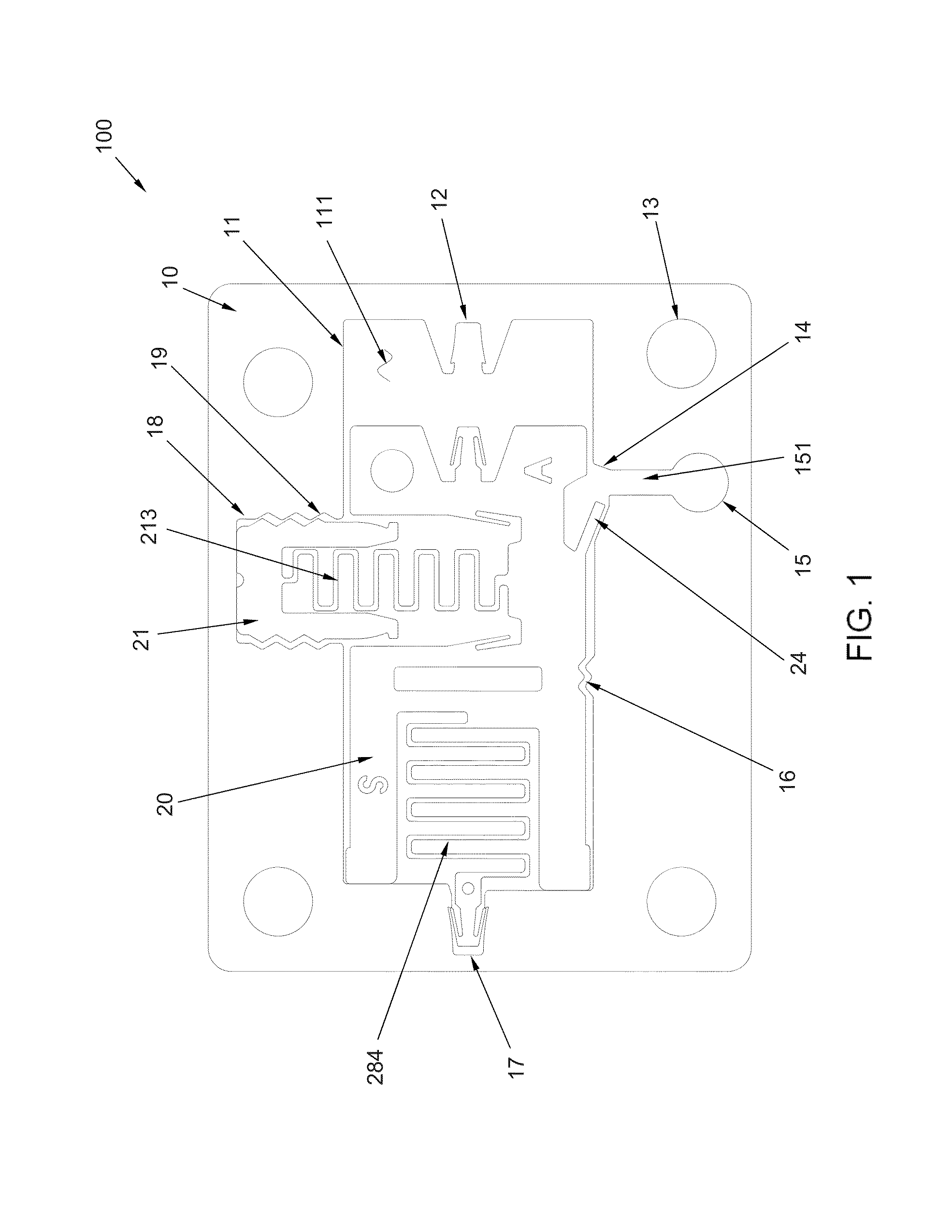
[0033]the invention is shown in FIGS. 1 through 9.

[0034]The safety of the safety and arming device of a fuze derives from the highly selective mechanical and electro-mechanical logic intrinsic to the design. As will be described, environmental stimuli of unique direction, threshold, sequence, and duration are necessary to effectuate the arming sequence in the mechanical logic. Environmental inputs that do not match the launch / dispense sequence result in one of two outcomes: a) the mechanical logic elements may partially respond to the inputs and then reset to their original “safe” (unarmed) position, or b) the mechanical logic elements may partially respond to the inputs and due to the out-of-sequence or improper nature of the inputs the mechanical elements may finish in a “failed safe” condition.

Description of the S&A Assembly and Explosive Train

[0035]The core of the inventive design is the miniature safety and arming mechanism 100, preferably fabricated using micro-machining or ME...

third embodiment

Description of Third Embodiment, Rotating 3rd S&A Interlock

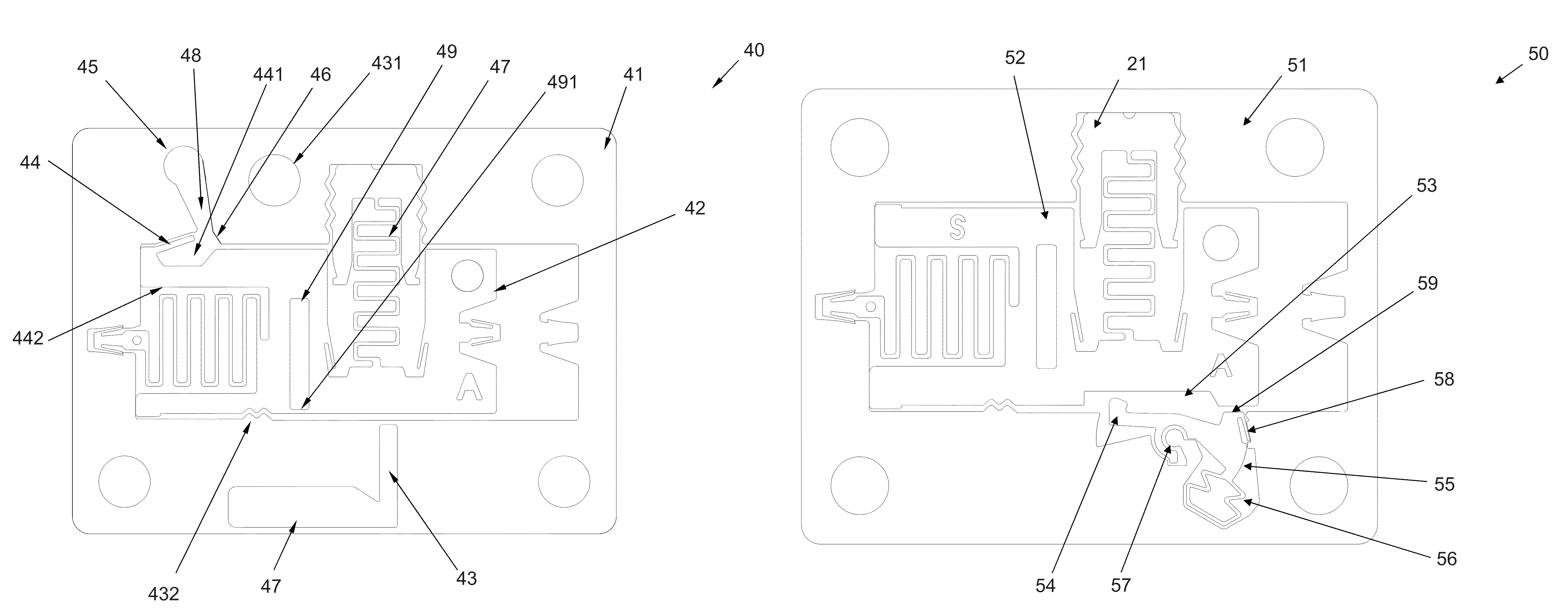
[0056]In a third embodiment, FIG. 11, an S&A mechanism 50, analogous to 100 in the first embodiment, incorporates a modified frame 51, a modified arming slider 52 with a rotor recess 53, and a bellows-rotor assembly 55 consisting of a rotor head 54, rotor latch 58, rotor tab 59, actuator bellows 56, and actuator pivot assembly 57. The electromechanical logic of this third embodiment is the same as for the first embodiment, but the means of implementation depends in this embodiment on the command initiator bridge and spot charge 332 output gas-expansion to expand bellows 56 and rotate the rotor of rotor assembly 55 to remove the second safety lock from the modified arming slider and the operation of a bellows and a rotor latch. The bellows-rotor assembly fits into a matching socket suitably fabricated into the modified frame 51 such that a pivot assembly 57 is operable to permit the rotor assembly to rotate enough to change i...


PUM


Abstract

An ultra-miniature, electro-mechanical, MEMS type safe and arming (S&A) device for medium- or large-artillery rounds, including, three sequenced S&A interlocks: a setback slider which provides a 1st interlock with respect to an arming slider which moves due to the round's spin; a stop and release mechanism that holds the arming slider until a release command signal is initiated by the fuze circuit, triggering a spot charge which generates an expanding gas wave that flexes the latch arm from contact with the safety catch, unlocking the 2nd interlock, thereby freeing the arming slider to continue its motion into an arming position, unlocking the 3rd interlock, and aligning the parts of the firetrain within the device, such that upon signal from the fuze circuit to an output charge, the device will ignite the acceptor charge within the round.

Description

CROSS-REFERENCE TO RELATED APPLICATIONS[0001]This application is a divisional application of U.S. patent application Ser. No. 12 / 434,093, filed on May 1, 2009 now U.S. Pat. No. 8,276,515, where both this application and the currently copending Ser. No. 12 / 434,093 application claim the benefit under 35 USC §119(e) of U.S. provisional patent application 61 / 049,585, filed on May 1, 2008, which provisional application is hereby incorporated by reference.FEDERAL RESEARCH STATEMENT[0002]The inventions described herein may be manufactured, used, and / or licensed by the U.S. Government for U.S. Government purposes.FIELD OF THE INVENTION[0003]The present invention relates to a safety and arming mechanism for munitions, and more particularly to munitions which are tube-launched, high-acceleration, high-spin, medium- or large-caliber rounds.BACKGROUND OF THE INVENTION[0004]The premature detonation of munitions, including artillery rounds, bombs, missiles, and / or mortar shells during handling, s...

Claims


Application Information

Patent Timeline
Patent Type & Authority Patents(United States)
IPC IPC(8): F42C15/26
CPCF42C15/005F42C15/22F42C15/24F42C15/26F42C15/30F42C15/34
Inventor ROBINSON, CHARLES H.WOOD, ROBERT H.GELAK, MARK R.HOANG, THINH Q.SMITH, GABRIEL L.
Owner UNITED STATES OF AMERICA THE AS REPRESENTED BY THE SEC OF THE ARMY
Why Eureka
Try Eureka