Aircraft generating a lift from an interior thereof

a technology of aircraft and lift, applied in the field of aircraft, can solve the problems of greatly reduced fluid resistance, and achieve the effects of reducing energy, reducing energy consumption, and reducing energy consumption

Active Publication Date: 2013-05-28
ZHU XIAOYI
View PDF12 Cites 32 Cited by
  • Summary
  • Abstract
  • Description
  • Claims
  • Application Information

AI Technical Summary

Benefits of technology

[0008]The object of the invention aims at resolving the main technical problem, and thus provides an aircraft with a bigger lift from its interior, greatly reduced fluid resistance, effectively improved speed and power efficiency, significantly reduced energy consumption, and simplified structure, which can be achieved by modifying a conventional aircraft vehicle.

Problems solved by technology

1. There is a fluid channel within the aircraft fuselage. On an upper surface of the fuselage is located at least one port with a fluid channel communicated with an engine. With the action of powerful suction of the engine, an external fluid each the engine through the internal fluid channel from the port on the upper surface. Because of the long path length, large area and fast fluid speed from the port to the engine, the pressure is naturally low. Such a powerful suction state of the engine forces the fluid to rapidly fast flow through the fluid channel, resulting in a huge lift inside the aircraft and then onto the upper external surface thereof. There generates a tremendous pressure difference between the upper external surface and a lower external surface of the aircraft on which the fluid flows at normal speed. This pressure difference creates a great life which is controllable through the engine or the port.
2. In the course of lift generation for a new aircraft, the ports at the front-end and around the fuselage communicate with the fluid channel and the exits at the back-end. Thereby, the fluid resistance at the fluid wall and the fluid hole is drained out from the exits to avoid the fluid hole from being blocked, changing the fluid distribution. The fluid resistance is therefore greatly reduced.

Method used


Image

  • Aircraft generating a lift from an interior thereof
  • Aircraft generating a lift from an interior thereof
  • Aircraft generating a lift from an interior thereof

Examples


first embodiment

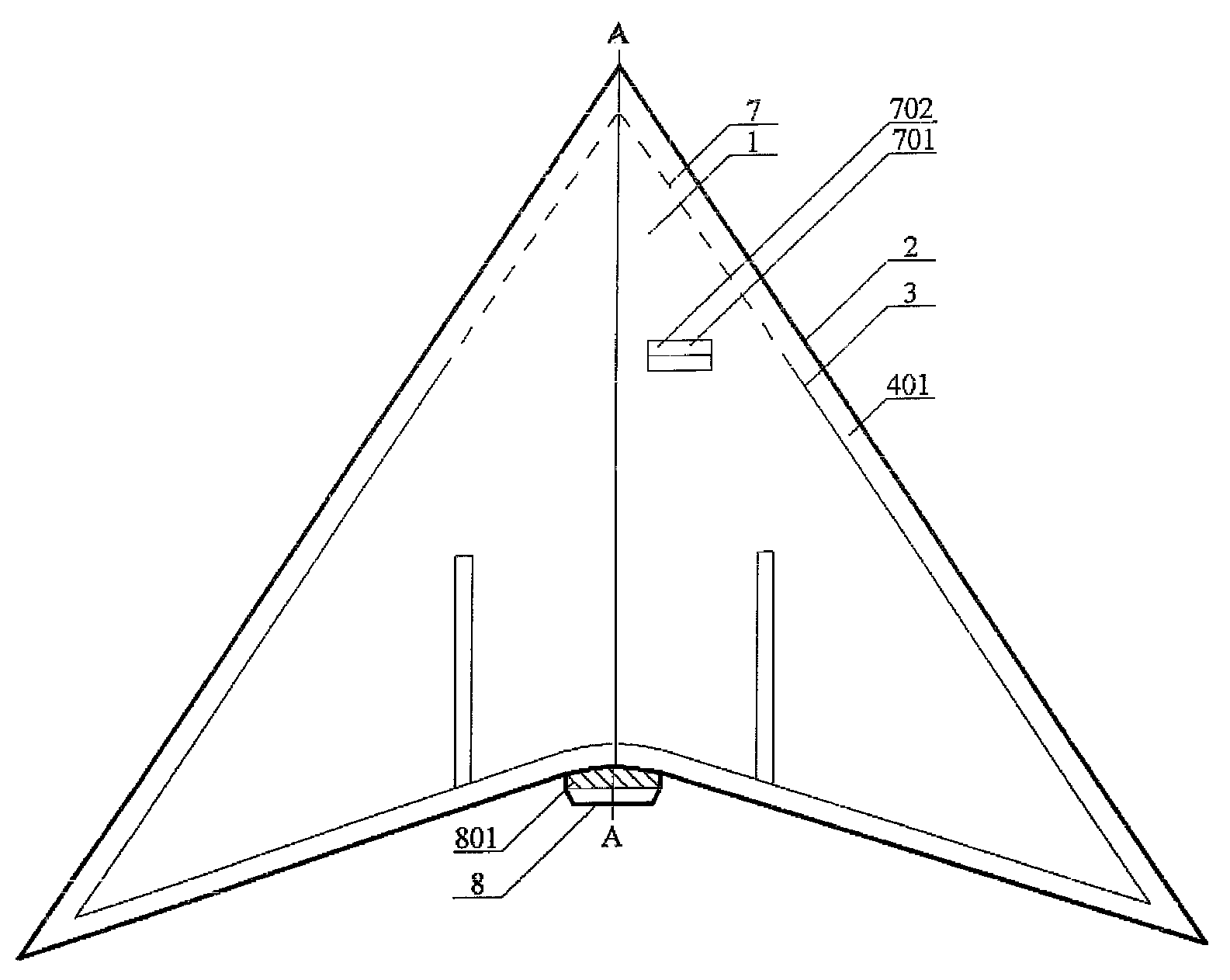
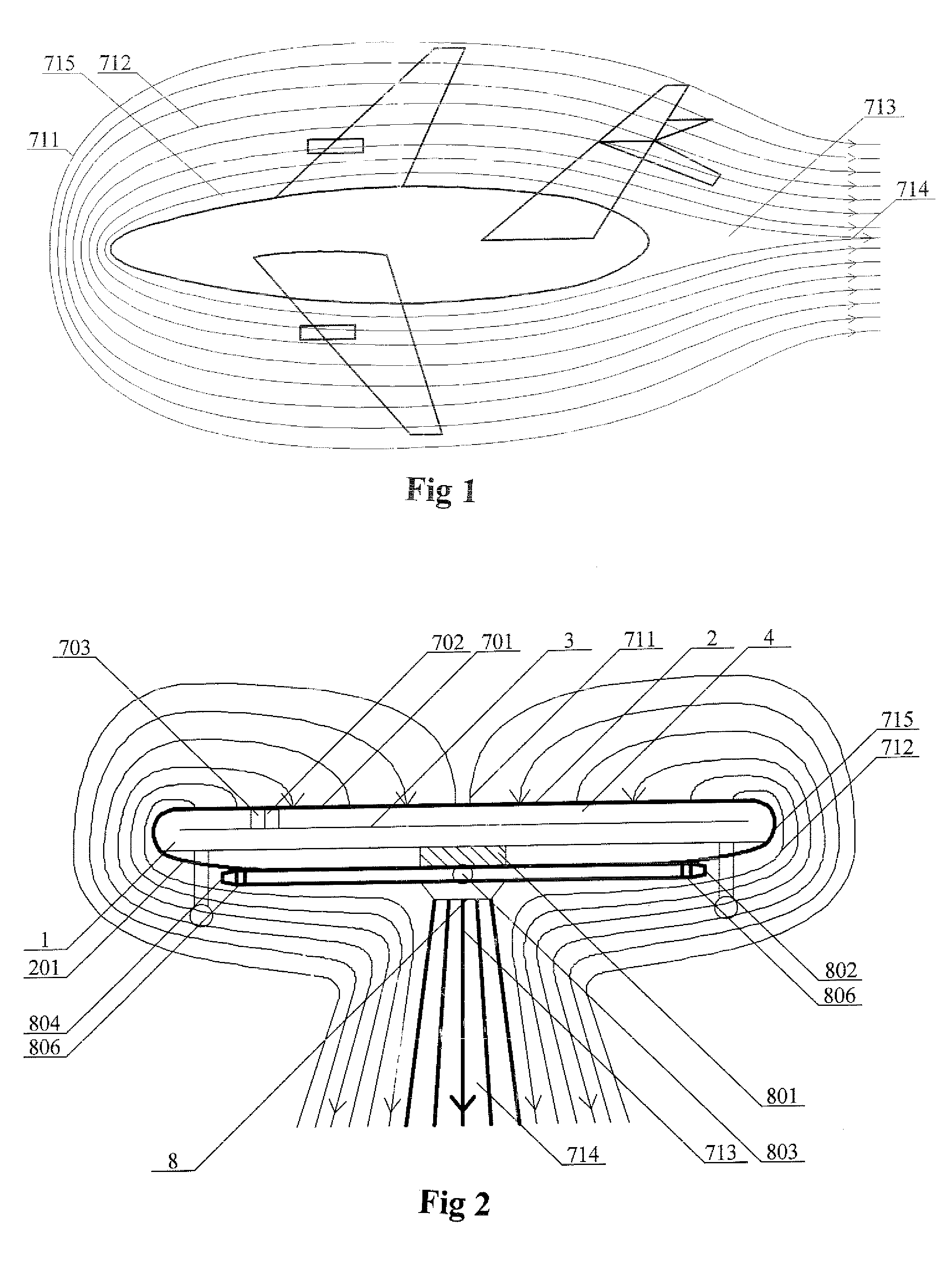
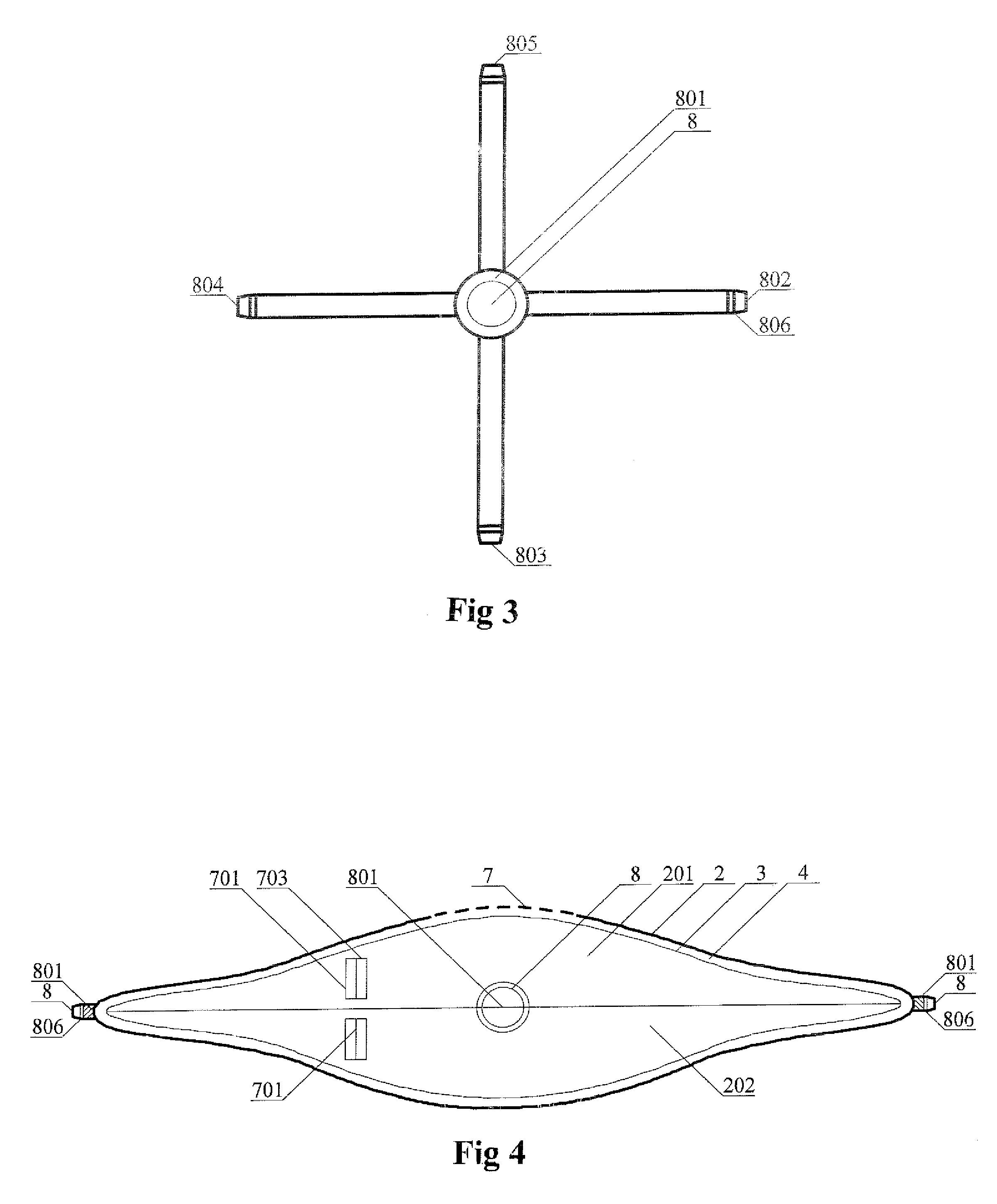
[0071]In the first embodiment, as shown in FIG. 2 and FIG. 3, a flight equipment main body 1 includes an outer shell 2 and inner shell 3. The inner shell 3 communicates with a fluid channel 4 having at least one partition. On an upper surface of the outer shell 2 is located at least one first port 701 or on a periphery of the outer shell 2. Each of the first port 701 and the second port 702 has a controller 703 to control a spoiler panel which has a curved upper surface and a flat lower surface which can act like a shutter when close or open. The upper and lower surfaces of the spoiler panel are feathery. As shown in FIG. 17, when the fluid flows in the port through the curved surface of the feathery spoiler panel, the flow path becomes longer, the fluid flows faster with lowered resistance. At the middle of the bottom of the outer shell is equipped with a jet engine 801. The jet engine 801 has an air-in vent communicating with the fluid channel 4, and an air-out vent communicating ...

second embodiment

[0083]In a forth embodiment, a garment-shaped flight vehicle, namely, flight suit, as shown in FIG. 3 and FIG. 8, has the same structure as the second embodiment, except that the flight vehicle has a fluid channel 401 between an outer covering 2 and an inner covering 3 to communicate with the fluid channel 4 in the equipment main body. At least one controller 703 is located on the outer covering 2 to control the air-in angle of the ports 701, 702 communicating with the fluid channel 401. A holder 9 is located at each of the right-hand side and the left-hand side for the user to conveniently hold and keep them balanced. The holders can be also mounted at front and rear of the equipment main body. The inner covering 3 is impermeable for water and air. The outer covering 2 is thoroughly feathery, as shown in FIG. 17, in order to reduce the fluid resistance.

[0084]When the jet engine 801 works the generated huge suction powerfully drains the external fluid into the fluid channel 4 throug...


PUM


Abstract

The invention discloses an aircraft generating a larger lift from its interior. The fluid channel inside the aircraft communicates with the engine and the ports on the upper surface of the outer shell. With the powerful suction of the engine, the fluid on the upper surface of the outer shell is quickly sucked into the fluid channel via respective ports under conditions of long path, large area, high speed and low air pressure, which results in large lift from the interior of the aircraft. In the course of generating the lift, the fluid resistances of the fluid wall and the fluid hole are sucked into the fluid channel through the ports at the front and the surrounding area of the aircraft, then high-speed fluid is emitted from the rear port. This approach contributes greatly to the transformation of the existing aircraft. The unified big wing significantly improves the lift, the speed and the carrying capacity of the existing aircraft with lowered energy consumption.

Description

BACKGROUND OF THE INVENTION[0001]1. Field of the Invention[0002]This invention relates to an aircraft, especially to an aircraft with more power lift.[0003]2. Related Prior Art[0004]Aircraft has been around for about a hundred years. Its lift force comes from a propeller and wings which produce limited lift force with high energy consumption. However, this invention is an aircraft having no wing and propeller but generating greater lift from its interior. In the course of generating the lift, the fluid resistance significantly reduces. This method modifies the traditional aircraft to improve lift and speed while reduce power consumption.[0005]Conventional prior art discloses the proposed vehicle was in fluid-hole large negative pressure zone formed by closing a fluid wall, a fluid hole, and a fluid mouth, the fluid resistance of a moving car can be greatly reduced as long as the fluid hole mouth can be avoided to be closed.[0006]Through a further study, it is found that a vehicle bo...

Claims


Application Information

Patent Timeline
Patent Type & Authority Patents(United States)
IPC IPC(8): B64C15/00
CPCB64C3/141B64C39/00B64C39/001B64C39/026Y02T50/12Y02T50/10
Inventor ZHU, XIAOYI
Owner ZHU XIAOYI
Why Eureka
Try Eureka