
Portable coagulation monitoring device and method of assessing coagulation response

a monitoring device and a technology of coagulation, applied in the field of portable coagulation monitoring devices and methods of assessing coagulation response, can solve the problems of adverse results for patients, inability to allow mechanical activation, and the need for intensive laboratory training and upkeep for pfa-100, so as to achieve greater platelet response, high shear rate, and high shear rate

Active Publication Date: 2013-05-28
ENTEGRION INC
View PDF8 Cites 12 Cited by
  • Summary
  • Abstract
  • Description
  • Claims
  • Application Information

AI Technical Summary

Benefits of technology

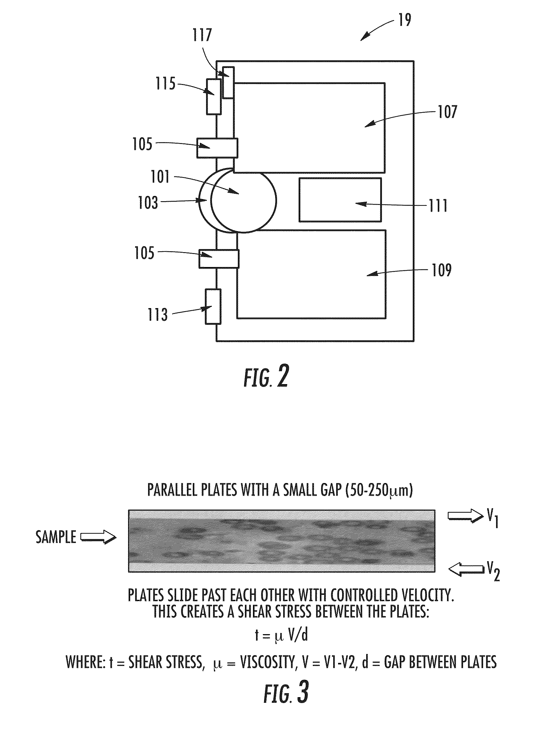
[0015]More specifically, the device allows for the measurement of coagulation response based on the knowledge that the biophysical response of blood depends in part on the relative shear rate between the blood and surfaces with which it is in contact. More specifically, the higher the shear rate, the greater the platelet response so that the platelets then stick to the surfaces of the plates, and thereby trigger the fibrin polymerization and couple the motion of the two plates when only one is driven by the motors. More specifically, it is recognized that in hemorrhaging events platelets need to react quickly so the use of a high shear rate for a short time period can allow accurate assessment of platelet response for these conditions. Thereafter, lower shear rates can be employed in terms of relative movements of the plates or members with respect to each other, to obtain an accurate assessment of fibrin response, or at an intermediate shear rate, both fibrin and platelet response.

Problems solved by technology

It does not measure platelet adhesion, only polymerization of fibrin, and does not allow for mechanical activation of the coagulation response through shear forces.
Thus, the information obtained from a TEG analysis falls far short of our current understanding of coagulation response, and requires excessive amounts of time which could result in inappropriate treatment for trauma being applied, leading to adverse results to a patient, possibly even death.
The use of such devices as TEG and the PFA-100 requires intensive laboratory training and upkeep, and they are not easily used in the field.

Method used


Image

  • Portable coagulation monitoring device and method of assessing coagulation response
  • Portable coagulation monitoring device and method of assessing coagulation response
  • Portable coagulation monitoring device and method of assessing coagulation response

Examples


Embodiment Construction

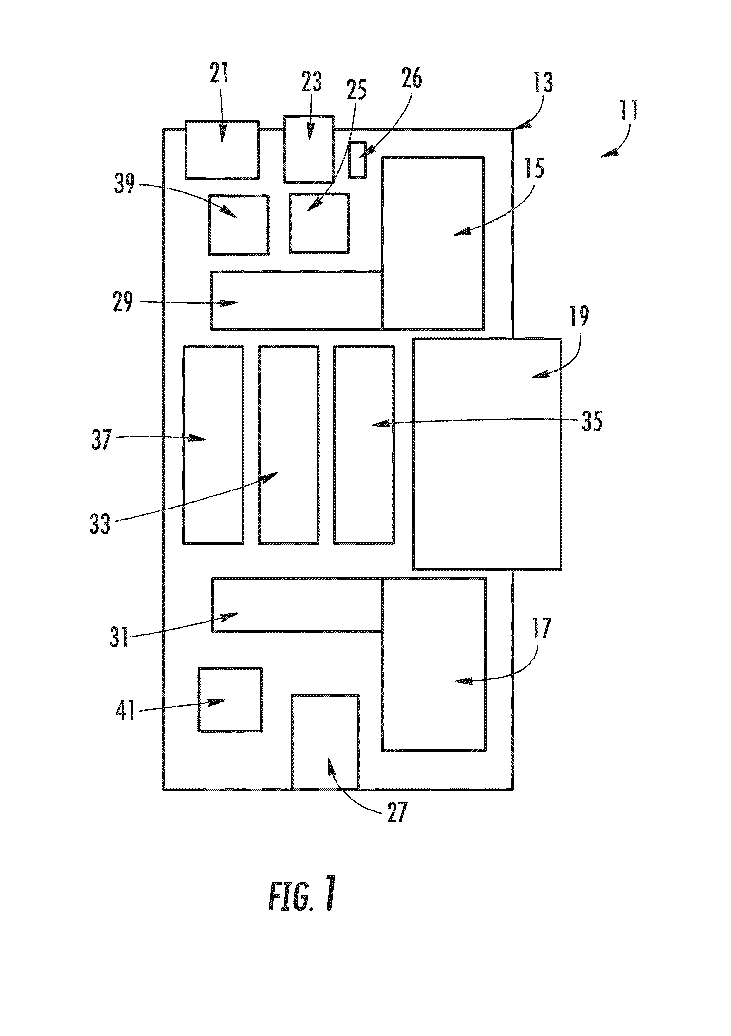
[0029]FIG. 1 illustrates in schematic form an exemplary portable coagulation monitor or assay device 11 for diagnosis of trauma or other related coagulopathies in which it is important to assess coagulation response to optimize treatment, for example, in critical field situations wherein the first hour is critical in terms of preventing long-term debilitating events or even death.

[0030]The device is housed in an impact resistant housing 13 which has all the components housed thereon in a conventional manner.

[0031]At least one and preferably a pair of linear voice coil actuator motors 15 and 17 are provided for driving movement of sample plates in a removable blood sample cassette which is illustrated in greater detail in FIG. 2. While the motors 15 and 17 and removable blood sample cassette 19 have been described briefly, the remaining components are discussed generally with reference to the drawings in a clockwise manner beginning with the data card port 21 in the upper left-hand c...


PUM

PropertyMeasurementUnit
transparentaaaaaaaaaa
volumesaaaaaaaaaa
pHaaaaaaaaaa

Abstract

A device, system and method is disclosed in which small volume blood samples are subjected to shear forces and shear stresses between two parallel planar surfaces to which linear motion trajectories are imparted. The formation of clots or coagulation of the sample is measured from dynamic mechanical coupling which occurs between the two parallel planar surfaces. Detection of the coagulation response can be achieved through optical probing or by measurement of physical effects of the blood sample binding to the planar surfaces, and restricting movement thereof.

Description

CROSS REFERENCE TO RELATED APPLICATIONS[0001]This application is related to and claims priority to U.S. Provisional Application Ser. No. 61 / 287,780 filed Dec. 18, 2009, the disclosure of which is expressly incorporated herein in its entirety.FIELD OF THE INVENTION[0002]The invention relates to a device, and method which allows rapid assessment of coagulation response. More particularly, the invention relates to such a device and method which provides extensive and complex information on coagulation response, including platelet function and fibrin polymerization to allow selection of appropriate treatment protocols, in particular for trauma induced coagulopathies but also for the diagnosis of hereditary or acquired abnormalities of coagulation, such as von Willebrand disease or hemophilias.BACKGROUND OF THE INVENTION[0003]The process by which the body prevents blood loss is referred to as coagulation. Coagulation involves the formation of a blood clot (thrombus) that prevents further...

Claims


Application Information

Patent Timeline
Patent Type & Authority Patents(United States)
IPC IPC(8): C12Q1/56
CPCG01N21/17G01N33/4905G01N33/86G01N2011/008
Inventor DENNIS, ROBERT GLENNFISCHER, THOMAS H.DACORTA, JOSEPH ANTHONY
Owner ENTEGRION INC
Learn More