Controlling system for controlling an air handling system

a control system and air handling technology, applied in computer control, adaptive control, instruments, etc., can solve the problems of inability to measure in the cabin air or in the air entering the cabin via the air handling unit, and achieve the effect of increasing functionality

Active Publication Date: 2013-05-28
KONINK PHILIPS ELECTRONICS NV
View PDF16 Cites 12 Cited by
  • Summary
  • Abstract
  • Description
  • Claims
  • Application Information

AI Technical Summary

Benefits of technology

[0009]It is an object of the invention to provide a controlling system of the kind set forth in the opening paragraph which has an increased functionality.

Problems solved by technology

Furthermore, the known sensor system is only capable of measuring in the outside air entering the air handling unit but is incapable of measuring in the cabin air or in the air entering the cabin via the air handling unit.

Method used


Image

  • Controlling system for controlling an air handling system
  • Controlling system for controlling an air handling system
  • Controlling system for controlling an air handling system

Examples


first embodiment

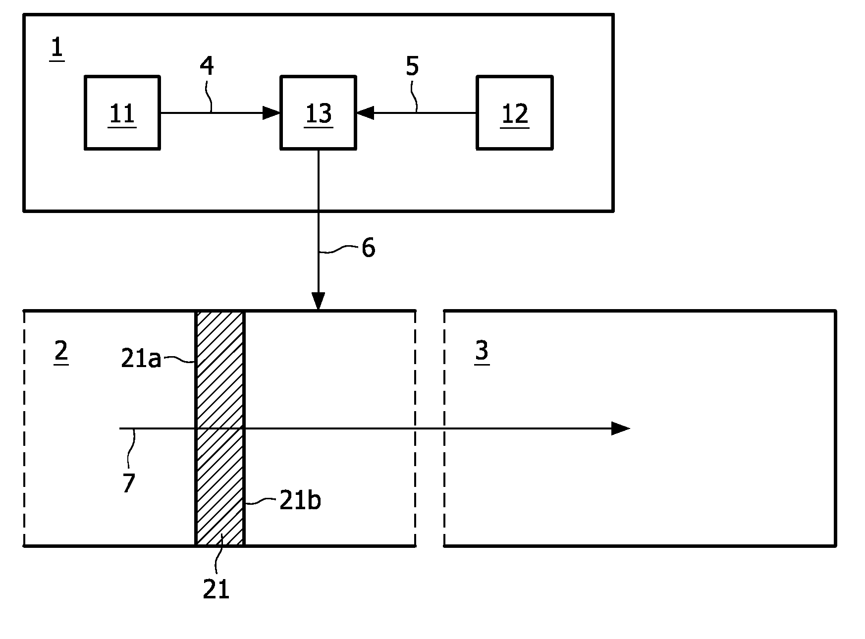
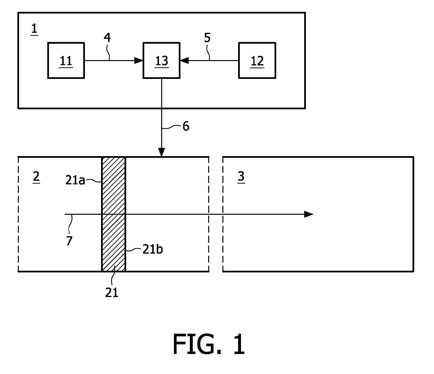
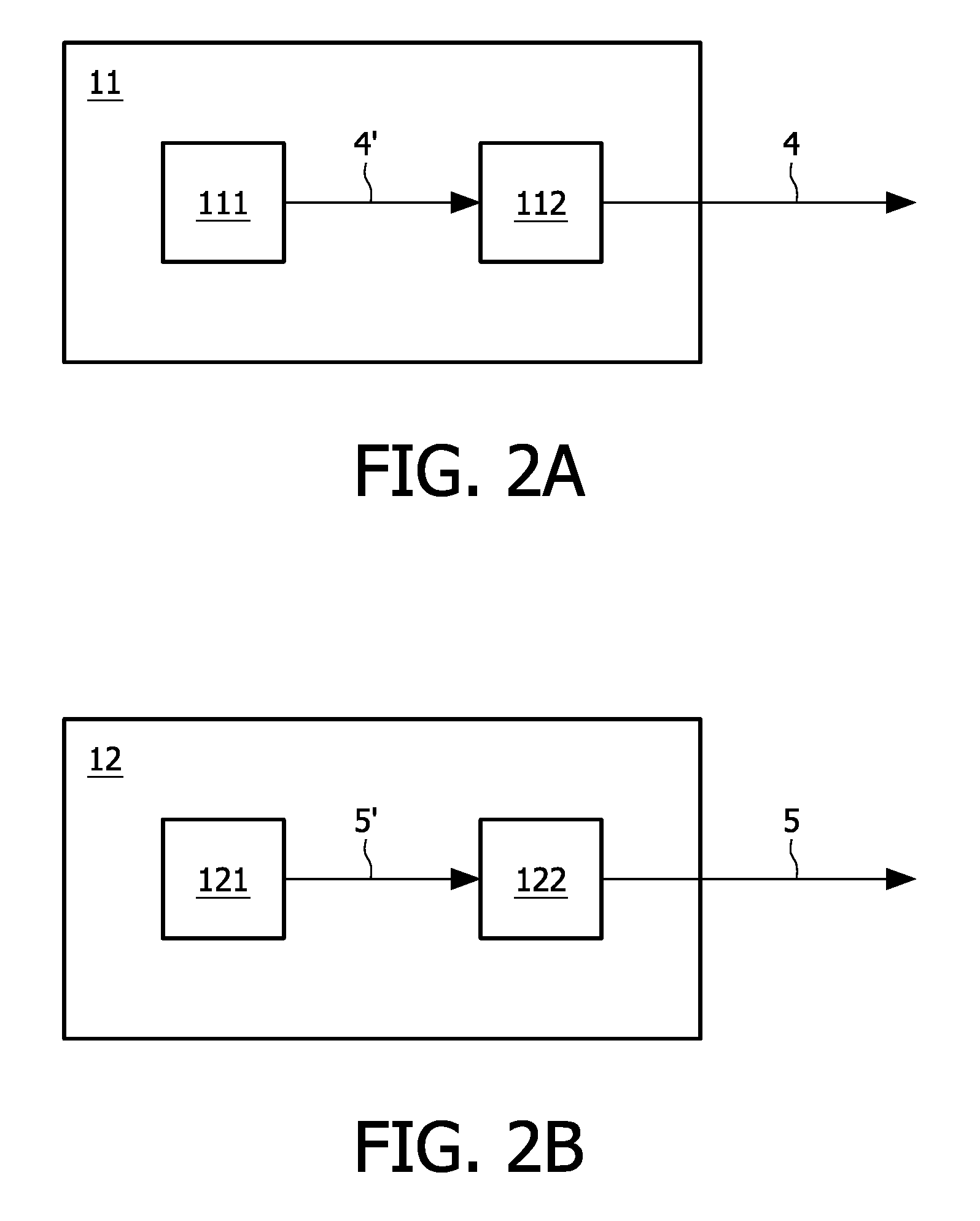
[0040]As shown in FIG. 4, the second sensing unit 12 is arranged to perform the second measurement in air at the downstream side 21a of the air cleaning unit 21. In a first embodiment, shown FIG. 4A, the second sensing unit 12 is arranged to perform the second measurement inside the air handling system 2. Although in FIG. 4A, the complete second sensing unit 12 is shown to be present inside the air handling system 2, this embodiment is not restricted to such an arrangement. One can also have only the second sensor 121 present inside the air handling system 2, or one can have the complete second sensing unit 12 outside the air handling system 2 and use means to duct air from the part of the air handling system 2 at the downstream side 21b of the air cleaning unit 21, to the second sensing unit 12. In this embodiment, the first output signal 4 and the second output signal 5 can be checked on their mutual consistency and compatibility, thereby obtaining early fault diagnosis and an inc...

second embodiment

[0041]In a second embodiment, shown in FIG. 4B, the second sensing unit 12 is arranged to perform the second measurement inside the enclosure 3. This embodiment is particularly useful when an air pollution source is present inside the enclosure 3. In this case the second output signal 5 does not necessarily correlate with the first output signal 4, and the air handling system 2 can be switched into an outside-air-inlet mode when the second sensing unit 12 signals the existence of a high concentration of certain airborne pollutants that have not entered the enclosure 3 via the air handling system 2.


PUM


Abstract

The invention relates to a controlling system for controlling an air handling system that is arranged to handle air in an enclosure such as a cabin of a vehicle. The controlling system comprises a first sensing unit, a second sensing unit, and a controller. The first sensing unit is arranged to generate a first output signal based on a measurement of the 5 concentration of certain airborne pollutants at the upstream side of an air cleaning unit that is comprised in the air handling system. The second sensing unit is arranged to generate a second output signal based on a measurement of the concentration of certain airborne pollutants at the downstream side of the air cleaning unit. The first output signal and the second output signal are used for specific purposes in a decision-making process that can be 10 performed by the controller. The controller is arranged to switch the air handling system into recirculation mode when the first output signal exceeds a predetermined threshold value. Furthermore, the controller is arranged to fine-tune settings of the air handling system, such as the mixing ratio of air admitted from outside the enclosure and recirculating air from the enclosure in the total air flow passing through the air handling system when the air handling 15 system operates in an outside-air-inlet mode. The controlling system according to the invent ion has an increased functionality and can maintain an acceptable air quality inside an enclosed space under a large variety of circumstances.

Description

FIELD OF THE INVENTION[0001]The invention relates to a controlling system for controlling an air handling system, the air handling system comprising an air cleaning unit having an upstream side and a downstream side, the air cleaning unit being arranged to pass an air flow into an enclosure positioned at the downstream side of the air cleaning unit, the air handling system being arranged to operate in recirculation mode or in an outside-air-inlet mode, the controlling system comprising a first sensing unit and a controller, the first sensing unit being arranged to generate a first output signal based on a first measurement performed in air at the upstream side of the air cleaning unit, the controller being arranged to switch the air handling system into recirculation mode when the first output signal exceeds a predetermined threshold value.[0002]The invention also relates to a vehicle comprising a cabin and the controlling system, wherein the enclosure is the cabin.BACKGROUND OF THE...

Claims


Application Information

Patent Timeline
Patent Type & Authority Patents(United States)
IPC IPC(8): B60H1/00B61D27/00
CPCB60H1/00792B60H1/008B60H3/0608B60H3/0085B60H1/00849
Inventor MARRA, JOHAN
Owner KONINK PHILIPS ELECTRONICS NV
Why Eureka
Try Eureka