Shoe sole with reinforcing structure and shoe sole with shock-absorbing structure

a technology of reinforcing structure and shock absorption, which is applied in the field of shoe soles, can solve the problems that the reinforcing member cannot suppress the lowering of the foot arch, and achieve the effect of stabilizing the compression deformation member

Active Publication Date: 2013-06-04
ASICS CORP
View PDF25 Cites 58 Cited by
  • Summary
  • Abstract
  • Description
  • Claims
  • Application Information

AI Technical Summary

Benefits of technology

[0020]Therefore, the first object of the present invention is to provide a shoe sole with a reinforcing member capable of suppressing the lowering of the arch and the bending, wherein the mid sole is allowed to be twisted not only in the mid foot part but also in the rear foot part, while supporting the foot with the mid sole and the upper conforming to the foot.
[0118]With such a structure, where the joined portion of the holding member is formed in an arch shape, the bending rigidity of the holding member having a large Young's modulus is increased. Therefore, it is possible to enhance the shock-absorbing function or the repulsive function at the edge of the side surface or the back surface.

Problems solved by technology

Such a reinforcing member will not be able to suppress the lowering of the foot arch.

Method used


Image

  • Shoe sole with reinforcing structure and shoe sole with shock-absorbing structure
  • Shoe sole with reinforcing structure and shoe sole with shock-absorbing structure
  • Shoe sole with reinforcing structure and shoe sole with shock-absorbing structure

Examples


first embodiment

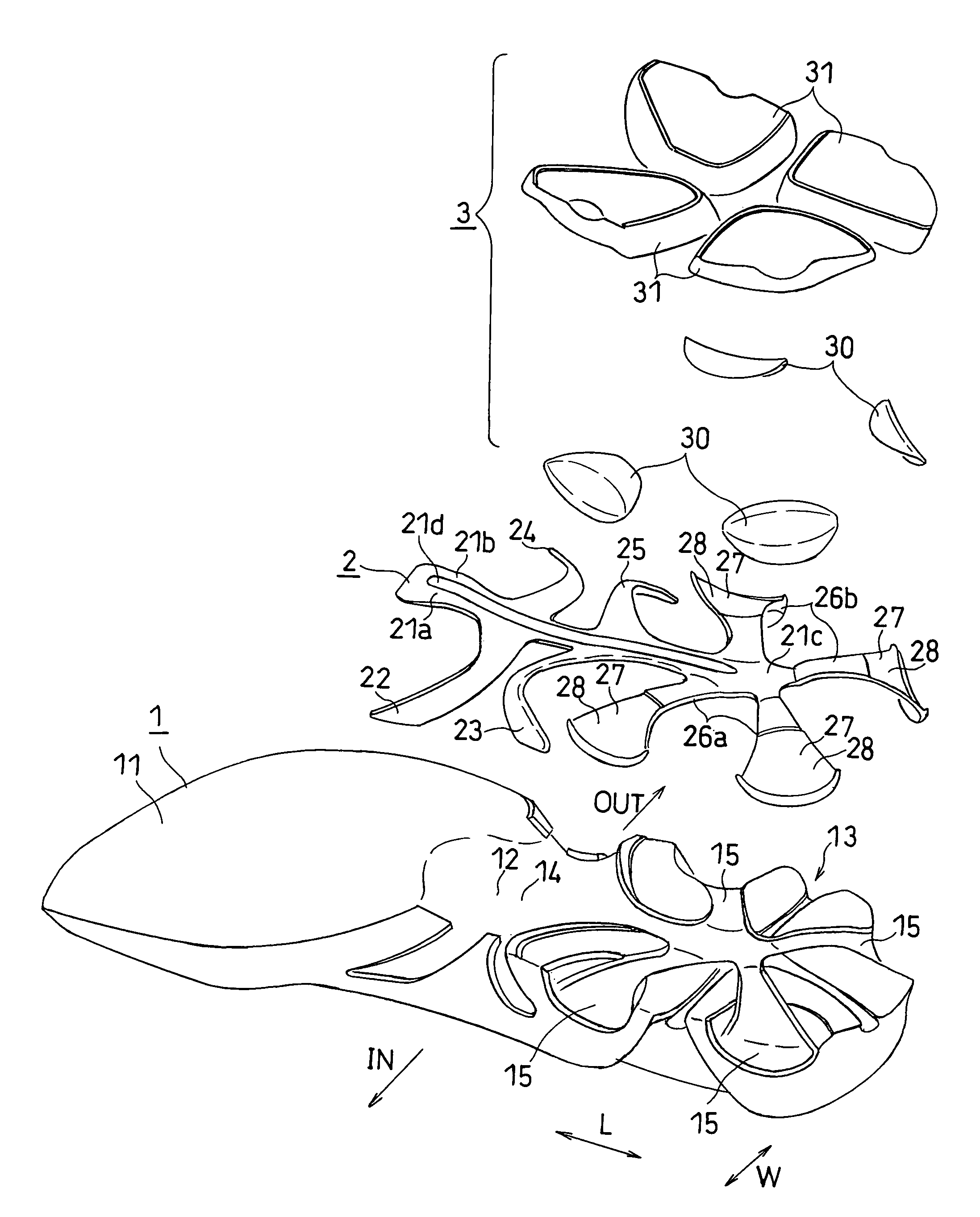
[0176]FIG. 1A to FIG. 7D each illustrates a first embodiment. In this and subsequent figures, “IN” and “OUT” denote the medial side and the lateral side of the foot, respectively. These figures show the structures while omitting design bumps / grooves. Such design bumps / grooves may be added as needed.

[0177]The following description is directed to a shoe sole for the left foot.

[0178]General Configuration:

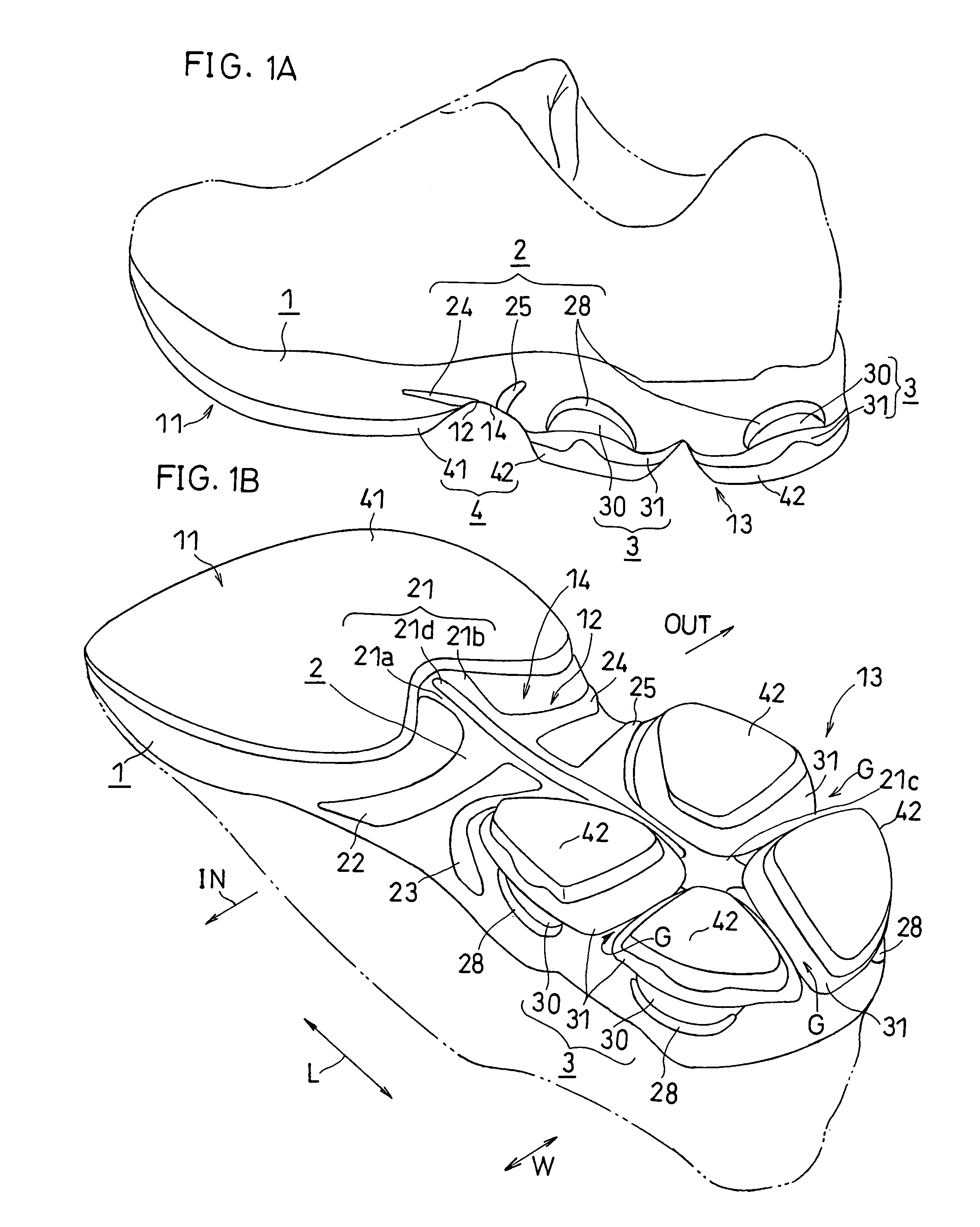
[0179]As shown in FIGS. 1A and 1B, a shoe sole of the present embodiment includes an upper mid sole 1, a reinforcing member 2, a lower mid sole 3 and an outer sole 4. In FIGS. 1A and 1B, a two-dot chain line represents the upper. The upper mid sole 1 and the lower mid sole 3 together form a mid sole. In a rear foot part 13, the lower mid sole 3 is divided into four portions.

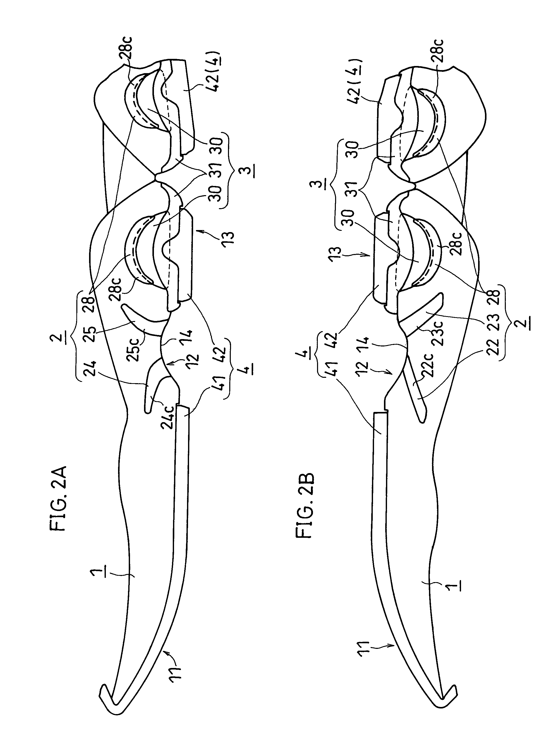
[0180]As shown in FIGS. 2A and 2B, the mid sole includes a fore foot part 11, a mid foot part 12 and the rear foot part 13.

[0181]The outer sole 4 is divided into a front outer sole 41 and a rear outer sole 42. The f...

second embodiment

[0249]A second embodiment will now be described with reference to FIG. 11A to FIG. 13B. In this and subsequent embodiments, like elements to those of the first embodiment are denoted by like reference numerals and will not be further described below.

[0250]As shown in FIGS. 11A and 11B, the compression deformation member 30 in the rear foot part is held between the upper mid sole 1 and the reinforcing member 2 in the present embodiment. The joined portion 27, to which the lower surface of the compression deformation member 30 is secured, is formed on the upper surface of the reinforcing member (the holding member) 2.

[0251]As shown in FIG. 12, in the present embodiment, there are a pair of compression deformation members 30, each being formed in a generally V-letter shape. The pair of compression deformation members 30, are arranged generally in symmetry. The joined portion 27 is also formed in a generally V-letter shape conforming to the shape of the compression deformation member 30...

third embodiment

[0253]Next, a third embodiment will be described with reference to FIGS. 15A and 15B.

[0254]As shown in FIGS. 15A and 15B, in the present embodiment, as opposed to the first embodiment, the rear foot blades 26a and 26b do not reach the side surface of the mid sole, whereby the edges of the rear foot blades 26a and 26b are not exposed on the side surface of the mid sole, and there is no first engagement portion.

[0255]On the side surface of the mid sole where the compression deformation member 30 is exposed, and in the vicinity thereof, the compression deformation member 30 is sandwiched between the upper and lower mid sole bodies 1 and 31. On the other hand, in areas where the rear foot blades 26a and 26b extend, the compression deformation member 30 is sandwiched and held between the holding member (reinforcing member) 2 and the lower mid sole body 31.

[0256]In the present embodiment, the outer sole 4 is rolled up along the side surface of the second engagement portion 32 of the lower...


PUM

PropertyMeasurementUnit
heightaaaaaaaaaa
rigidityaaaaaaaaaa
areaaaaaaaaaaa

Abstract

A shoe sole includes a mid sole, and a reinforcing member reinforcing a portion of the mid sole, wherein the member (2) extends over an area from a mid foot part (12) to a rear foot part (13), the member (2) including: a rod-shaped or strip-shaped main bar (21) provided along a line that is at the center of the foot; mid foot medial blades (22) and (23) and mid foot lateral blades (24 and 25) extending from the bar (21) in the part (12); a plurality of rear foot blades (26a and 26b) extending from the bar (21) in the part (13), wherein the blades (22 to 26b) are integral with the bar (21), the blades (22 to 25) are attached to a lower surface of the mid sole, and at least a portion of each of the blades (26a and 26b) is buried in the part (13).

Description

TECHNICAL FIELD[0001]The present invention relates to a shoe sole and, more particularly, to a reinforcing structure of a mid foot part and a shock-absorbing structure of a rear foot part.BACKGROUND ART[0002]Shoe soles having a reinforcing member conforming to the shape of the arch of the mid sole in an arch portion of the shoe soles, e.g., shoe soles in which a portion of the mid sole that is not attached to the outer sole does not touch the ground when the outer sole lands, are known in the art. Such a reinforcing member reinforces the rigidity of the arch portion of the mid sole by suppressing the deformation of the mid sole. The first to fourth patent documents, identified below, each disclose a known shoe sole structure with a reinforcing member, or the like.[0003][First Patent Document] Japanese Laid-Open Patent Publication No. 2000-287709 (Abstract)[0004][Second Patent Document] Japanese Laid-Open Patent Publication No. 63-194602 (FIG. 1, FIG. 2)[0005][Third Patent Document] ...

Claims


Application Information

Patent Timeline
Patent Type & Authority Patents(United States)
IPC IPC(8): A43B13/12A43B21/26A43B23/00A43B13/18
CPCA43B13/10A43B13/12A43B13/125A43B13/181A43B23/22A43B13/127
Inventor NISHIWAKI, TSUYOSHIKAYANO, TOSHIKAZUHAYASHI, TOMOHIROTAKEMURA, SHUHEI
Owner ASICS CORP
Why Eureka
Try Eureka